
Light emitting device

A technology for light-emitting devices and light-emitting elements, which can be used in optics, light guides, optical elements, etc., and can solve problems such as uneven brightness

Pending Publication Date: 2022-04-22
LEXTAR ELECTRONICS CORP
View PDF0 Cites 0 Cited by
  • Summary
  • Abstract
  • Description
  • Claims
  • Application Information

AI Technical Summary

Problems solved by technology

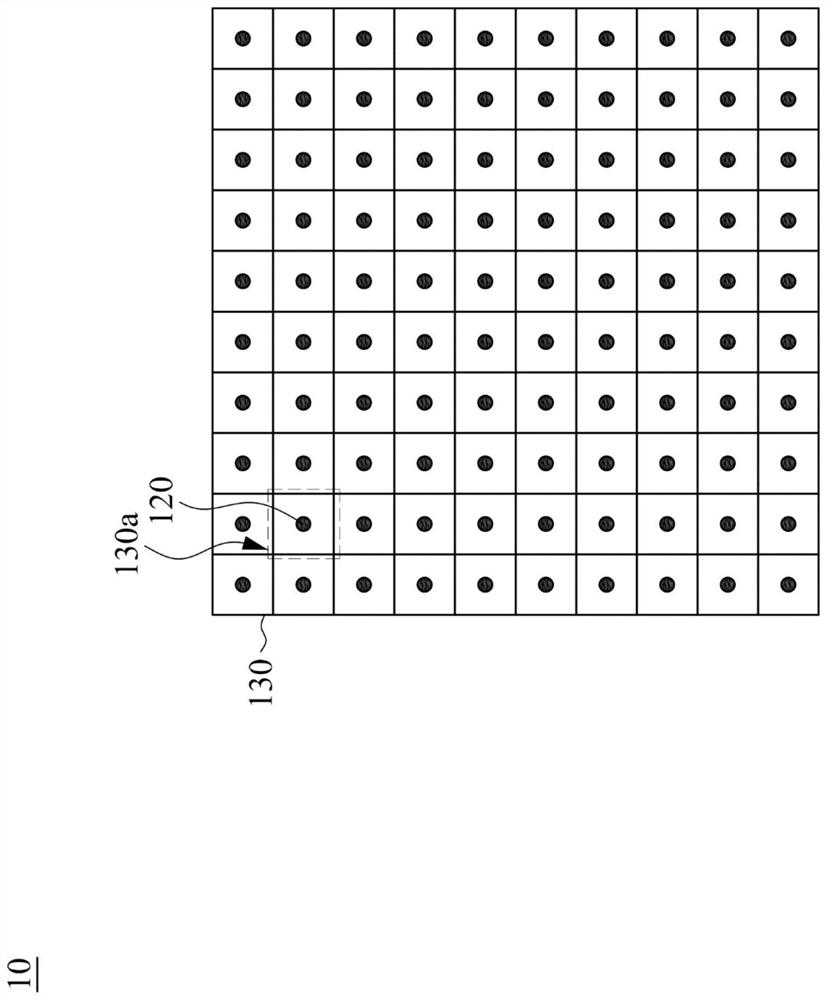
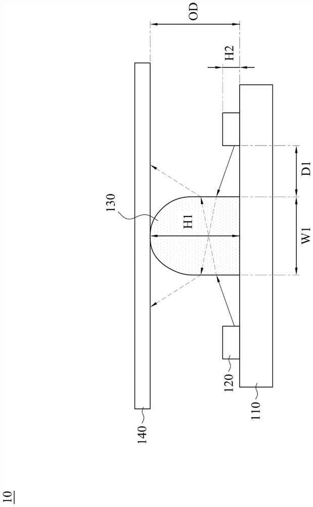
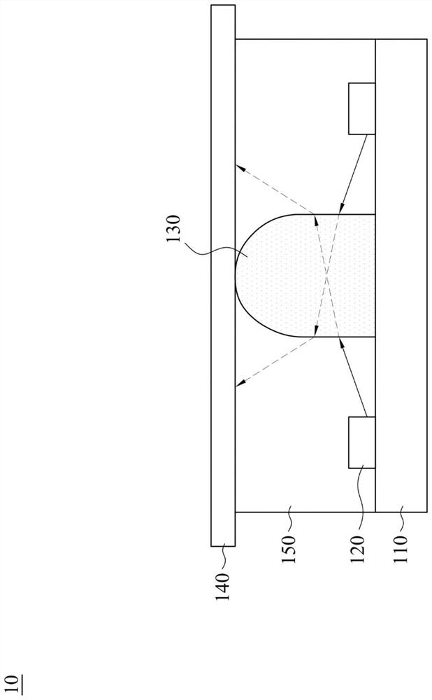
[0005] In order to solve the above problems, the present invention provides a light-emitting device, which can properly partially reflect, partially refract and partially transmit the light emitted by the light-emitting diodes through a special light-guiding structure, so that it can be achieved without increasing the number of light-emitting diodes and Improvement of brightness unevenness without increasing optical distance

Method used


Image

  • Light emitting device
  • Light emitting device
  • Light emitting device

Examples


Embodiment Construction

[0038] In order to make the description of the present invention more detailed and complete, the following provides an illustrative description of the implementation aspects and specific embodiments of the present invention; but this is not the only form for implementing or using the specific embodiments of the present invention. The embodiments disclosed below can be combined or replaced with each other when beneficial, and other embodiments can also be added to one embodiment, without further description. In the following description, numerous specific details will be set forth in order to enable readers to fully understand the following embodiments. However, embodiments of the invention may be practiced without these specific details.

[0039] In addition, spatially relative terms, such as "below", "above", etc., are for the convenience of describing the relative relationship between one element or feature and another element or feature in the drawings. The real meaning of...


PUM

PropertyMeasurementUnit
refractive indexaaaaaaaaaa

Abstract

A light-emitting device comprises a substrate, a plurality of light-emitting elements and a light guide structure. The light-emitting element is arranged on the substrate. The light guide structure is arranged on the substrate, the light guide structure separates the light-emitting element and continuously surrounds the light-emitting element, the light guide structure and the light-emitting element are separated from each other, light emitted by the light-emitting element can enter the light guide structure to enable the light guide structure to emit light, and the light guide structure is made of materials with the refractive index ranging from 1.1 to 3. According to the light guide structure, the light-emitting device can still have good brightness uniformity under the conditions that the number of the light-emitting diodes is greatly reduced and a thin diffusion structure is adopted.

Description

technical field [0001] The invention relates to a light-emitting device including a light-guiding structure. Background technique [0002] A display that cannot emit light by itself can use a backlight module to obtain a light source supply. In general, backlight modules can be classified into edge type and direct type. [0003] As far as the direct type backlight module is concerned, a diffuser is provided on the LED array to reduce the phenomenon of non-uniform brightness (Mura) when the display is displayed. In order to improve the phenomenon of uneven brightness, it may also be considered to increase the number of light emitting diodes or increase the optical distance (optical distance, OD). However, increasing the number of light emitting diodes will increase material costs and manufacturing costs. Increasing the optical distance will make the backlight module thicker, which is not conducive to the thinning of the backlight module. [0004] Therefore, how to improve...

Claims


Application Information

Patent Timeline
Patent Type & Authority Applications(China)
IPC IPC(8): H01L33/58H01L25/075
CPCH01L33/58H01L25/0753G02B6/0023G02B6/0068G02B6/0073G02B6/0065G02B6/0051G02F1/133603G02F1/133524
Inventor 邱一国赖隆宽陈廷楷林峻弘
Owner LEXTAR ELECTRONICS CORP
Learn More