


Quick Research
Generate reliable direction feasibility study reports for your R&D in just a few steps.

Technical Q&A
Discover and master advanced knowledge NOW. Basics, ideas, possibilities, all at once.

Find Solutions
As an expert in R&D theories, this can generate solutions to your technical problems instantly.

Evaluate Feasibility
Analyze your overall solution with one click, know your potential R&D risks in advance.

Monitor Landscape
Get weekly tech updates, stay abreast of the latest tech innovations and key insights.
Intelligent security window device based on hidden camera
An intelligent security and camera technology, applied in the arrangement of wing sashes, windows/doors, preventing theft, etc., to achieve the effect of improving safety, good concealment, and reducing mechanical impact
- Summary
- Abstract
- Description
- Claims
- Application Information
AI Technical Summary
Problems solved by technology
Method used
Image

Examples
Embodiment 1
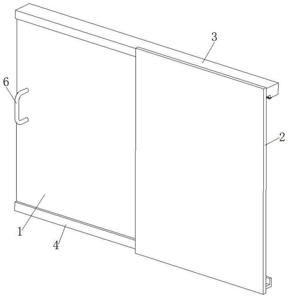
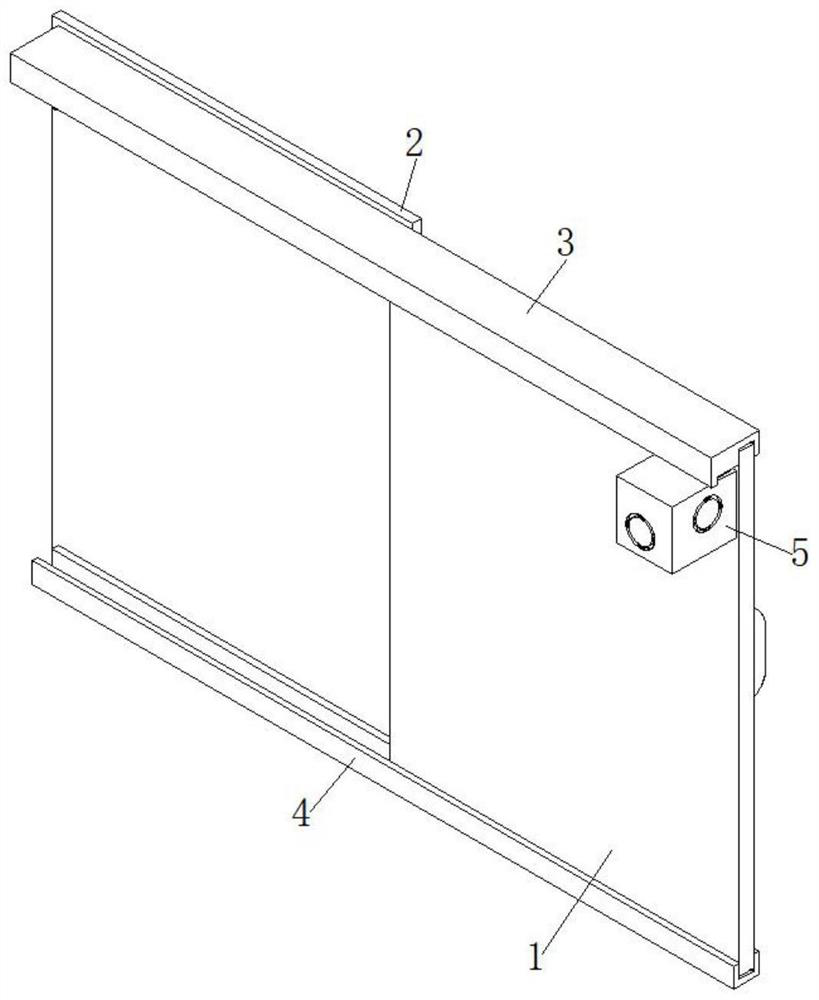
[0033] see Figure 1-5 As shown, the present invention is an intelligent security window device based on a hidden camera, comprising a security window 1 and a wall 2, the upper end of one side of the wall 2 is provided with a first support assembly 3, and one side of the wall 2 The lower end of the security window 1 is provided with a second support assembly 4, the security window 1 is slidably installed between the first support assembly 3 and the second support assembly 4, and a camera drive mechanism 5 is provided at the upper corner of the security window 1. The security window 1 is provided with a push-pull handle bar 6 . When the outsiders open the security window and enter the room, the camera in the camera driving mechanism 5 takes pictures of the outsiders, which improves the safety.
Embodiment 2
[0035] Based on the technical solution described in the first embodiment above. see Figure 6-8 As shown, the camera driving mechanism 5 includes an installation housing 501, the installation housing 501 is a hollow housing structure, and the installation housing 501 includes a first peripheral side plate 5011, a second peripheral side plate 5012, and a third peripheral side plate 5013 , the fourth peripheral side plate 5014 and the top plate 5015, and one side of the third peripheral side plate 5013 is fixedly connected with the upper corner of the security window 1 . The first rotating rod 502 and the second rotating rod 503 are rotatably connected between the first peripheral side plate 5011 and the third peripheral side plate 5013; Rotate lever 504 .
[0036] The ring side of the first rotating rod 502 is fixedly connected with a roller 505, the driving bevel gear 506 and the driving gear 507, and the ring side of the third rotating rod 504 is fixedly connected with a dr...
Embodiment 3
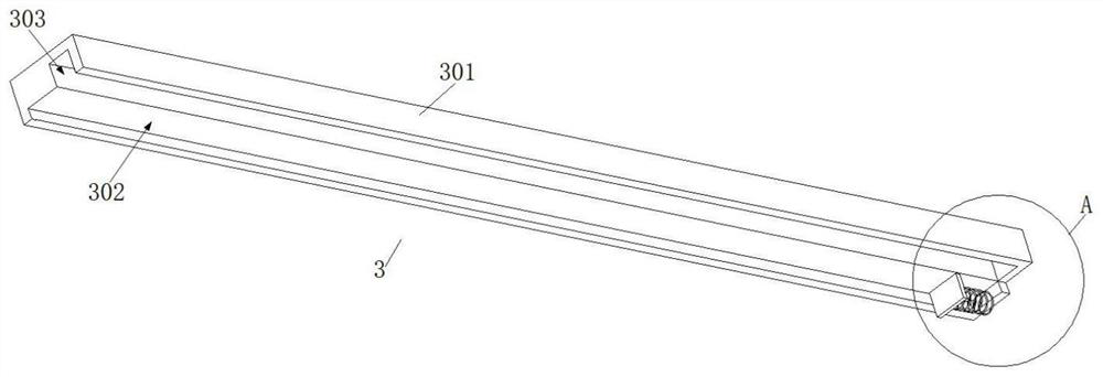
[0043] Based on the technical solution described in the second embodiment above. see image 3 with Figure 4 As shown, an inner wall of the first guide groove 302 is provided with a buffer spring 304 , and the other end of the buffer spring 304 is provided with a buffer plate 305 matched with the slider 518 to reduce the mechanical impact of the installation housing 501 .
PUM
 Abstract
Description
Claims
Application Information
 - R&D Engineer
- R&D Manager
- IP Professional
- Industry Leading Data Capabilities
- Powerful AI technology
- Patent DNA Extraction
Browse by: Latest US Patents, China's latest patents, Technical Efficacy Thesaurus, Application Domain, Technology Topic, Popular Technical Reports.
© 2024 PatSnap. All rights reserved.Legal|Privacy policy|Modern Slavery Act Transparency Statement|Sitemap|About US| Contact US: help@patsnap.com