
Rocket vertical landing guidance method considering thrust discontinuous instant adjustable

A non-continuous, thrust-adjusted technology, applied in self-propelled missiles, complex mathematical operations, offensive equipment, etc., can solve problems such as inability to adjust position and attitude, increase nonlinearity and complexity of guidance problems, and difficulty in precise landing guidance. Effects of improved efficiency, strong engineering applicability, enhanced guidance accuracy and robustness

Active Publication Date: 2022-04-19
BEIJING INSTITUTE OF TECHNOLOGYGY
View PDF6 Cites 2 Cited by
  • Summary
  • Abstract
  • Description
  • Claims
  • Application Information

AI Technical Summary

Problems solved by technology

Due to cost and technical constraints, the thrust of the engine actually used by the rocket can only be adjusted within a certain range. The minimum thrust is usually much greater than the rocket's own gravity, and the rocket itself cannot adjust its position and attitude through hovering and other actions.
Secondly, the rocket engine has many restrictions such as single thrust adjustment limit, thrust adjustment waiting interval, thrust establishment process, engine shutdown aftereffect, etc.
These limitations (collectively referred to as non-continuous real-time adjustable thrust) have greatly increased the nonlinearity and complexity of the guidance problem, and it is impossible to directly follow the existing convexization strategy and control variable processing method, which brings great difficulties to the application and solution of the convex optimization algorithm. It is a great challenge and brings great difficulties to precise landing guidance

Method used


Image

  • Rocket vertical landing guidance method considering thrust discontinuous instant adjustable
  • Rocket vertical landing guidance method considering thrust discontinuous instant adjustable
  • Rocket vertical landing guidance method considering thrust discontinuous instant adjustable

Examples


Embodiment Construction

[0028] The invention proposes a rocket vertical landing method considering the non-continuous and instantaneous adjustment of engine thrust. Method steps of the present invention are as follows:

[0029] Step 1, establishing a three-dimensional particle motion model for rocket return and landing guidance.

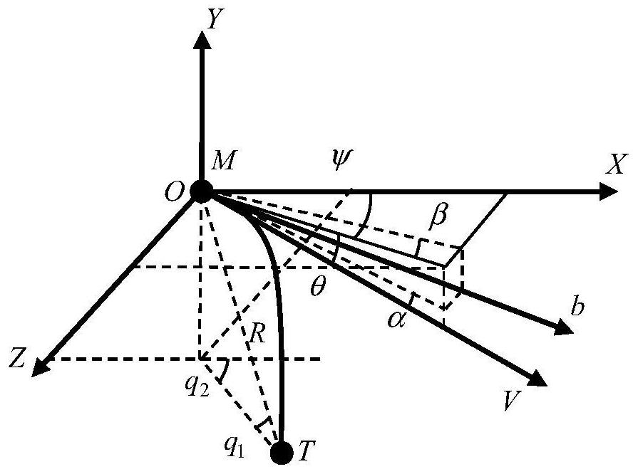
[0030] figure 1 The three-dimensional geometric relationship diagram of the rocket landing section is described. In the figure, OXYZ is the inertial coordinate system, M is the position of the rocket, T is the expected landing point of the rocket, Ob is the longitudinal axis of the rocket, R is the distance traveled by the rocket, and α and β respectively represent the attack distance. Angle and sideslip angle, q 1 is the angle between the line of sight and the horizontal plane, q 2 is the angle between the projection of the line of sight on the horizontal plane and the X axis, and V, θ and ψ represent the rocket's velocity, velocity inclination, and velocity deflection,...


PUM


Abstract

According to the rocket vertical landing guidance method considering the discontinuous instant adjustable engine thrust, the thrust instruction considering the engine thrust characteristic limitation can be planned in real time, and model prediction control of the landing point, the landing angle and the landing speed of a rocket body can be accurately controlled. The invention provides a rocket vertical landing guidance algorithm considering discontinuous and instant adjustment of engine thrust, a decoupling control strategy of tangential speed control and normal drop point and drop angle control is established, and an engine thrust instruction which is designed by utilizing an impulse conservation principle and meets actual thrust adjustment limitation is provided. According to the method, introduction of multiple complex and difficult-to-process nonlinear constraints is effectively avoided, the efficiency, convergence and reliability of convex optimization solution are improved, the guidance precision and robustness are remarkably enhanced, and higher engineering applicability is achieved.

Description

technical field [0001] The invention relates to the technical field of rocket guidance, in particular to a rocket vertical landing guidance method considering discontinuous and instant adjustable thrust. Background technique [0002] Reusable launch vehicles can effectively reduce launch costs and shorten launch cycles. During the return process of the rocket, it is necessary to use the limited control ability to achieve a wide range of power deceleration, to meet the constraints of the return process and the harsh fixed-point vertical soft landing terminal constraints (such as: position, speed, track angle, etc.), which has a great impact on the rocket’s return. Guidance and control present great challenges. Convex optimization has high efficiency and can handle various constraints such as process and terminal. It has been used more and more in trajectory optimization and guidance of rocket return. However, most of the existing convex optimization algorithms only consider ...

Claims


Application Information

Patent Timeline
IPC IPC(8): F42B15/01G06F17/11
CPCF42B15/01G06F17/11Y02T90/00
Inventor 熊芬芬李超赵越李泽贤
Owner BEIJING INSTITUTE OF TECHNOLOGYGY
Learn More