Road snow removing and ice breaking machine
A technology of snow plow and ice breaker, which is applied in snow surface cleaning, construction, cleaning methods, etc. It can solve the problems of less narrow road surface design of deicing devices and poor deicing efficiency, so as to increase the thickness of ice breaking, facilitate ice breaking, and Ease of cleaning
- Summary
- Abstract
- Description
- Claims
- Application Information
AI Technical Summary
Problems solved by technology
Method used
Image

Examples
Embodiment 1
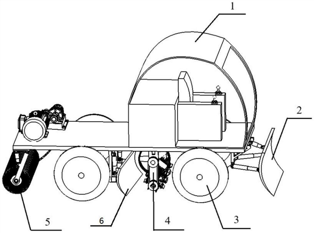
[0029] as attached figure 1 To attach image 3 As shown, the embodiment of the present invention provides a road snow removal and ice breaker, including a snow removal machine body 1, a driver's cab is arranged on the snow removal machine body 1, a snow removal assembly 2 and a driving device 3 are arranged on the bottom of the snow removal machine body 1, and the snow removal machine The bottom of the body 1 is also provided with a mechanical ice breaking mechanism 4;
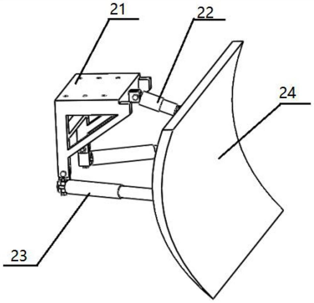
[0030] The snow removal assembly includes a mounting bracket 21, one side of the mounting bracket 21 is movably installed with a first hydraulic rod 22 and a second hydraulic rod 23, the length of the second hydraulic rod 23 is greater than the first hydraulic rod 22, the first hydraulic rod 22 and the second One end of the hydraulic rod 23 is movably connected with a snow removal shovel 24;
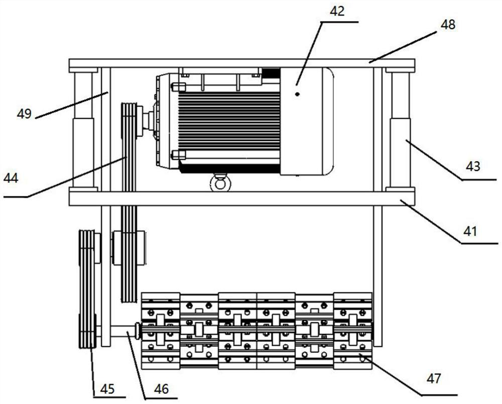
[0031] The mechanical ice breaking mechanism 4 includes a first vehicle frame 41, the top of the vehicle frame 41 is...
Embodiment 2
[0036] as attached figure 1 To attach Figure 4 As shown, the difference between the second embodiment and the first embodiment is that it is added: the bottom of the snow blower body 1 is provided with a snow clearing mechanism 5, the snow clearing mechanism 5 includes a second vehicle frame 51, and the top of the second vehicle frame 51 is provided with A reduction motor 52, the output end of the reduction motor 52 is fixedly sleeved with a first gear, the first gear meshes with a second gear, the second gear is connected with a third gear through a drive shaft, the third gear meshes with a large gear 53, and the large gear The inner wall of 53 is fixedly connected with driven shaft, and the outer wall of driven shaft is fixedly sleeved with drive sprocket 54, and the outer edge of drive sprocket 54 is meshed with chain 55, and the inner edge of chain 55 is meshed with driven sprocket 56, from One side of movable sprocket wheel 56 is fixedly equipped with snow sweeping roll...
Embodiment 3
[0040] as attached figure 1 to attach Figure 5 As shown, the difference between the third embodiment and the second embodiment is that it is added: the bottom of the snow plow body 1 is provided with a snow pushing mechanism 6, and the snow pushing mechanism 6 includes a guide rail 61, and one side of the guide rail 61 is movably installed with a Slider 63, one side of guide rail 61 is fixedly installed with snow clearing hydraulic rod 62, the bottom of snow clearing hydraulic rod 62 is fixedly connected with the top of slider 63, one side of slider 63 is detachably installed with inclined snow pusher 64.
[0041] Specifically, by setting the snow pushing mechanism 6, the snow can be concentrated and accumulated for subsequent cleaning, and the snow clearing hydraulic lever can be activated to move the inclined snow accumulation plate 64 downward, thereby adjusting the position of the inclined snow accumulation plate according to the thickness of the snow. Qingxue is more t...
PUM
 Abstract
Description
Claims
Application Information
 - R&D
- Intellectual Property
- Life Sciences
- Materials
- Tech Scout
- Unparalleled Data Quality
- Higher Quality Content
- 60% Fewer Hallucinations
Browse by: Latest US Patents, China's latest patents, Technical Efficacy Thesaurus, Application Domain, Technology Topic, Popular Technical Reports.
© 2025 PatSnap. All rights reserved.Legal|Privacy policy|Modern Slavery Act Transparency Statement|Sitemap|About US| Contact US: help@patsnap.com