A device for punching holes in the ice surface of fish ponds
A punching device, ice surface technology, applied in fishing, fishing accessories, applications, etc., can solve the problems of high work intensity, time-consuming and laborious, low efficiency, etc.
- Summary
- Abstract
- Description
- Claims
- Application Information
AI Technical Summary
Problems solved by technology
Method used
Image
Examples
specific Embodiment approach 1
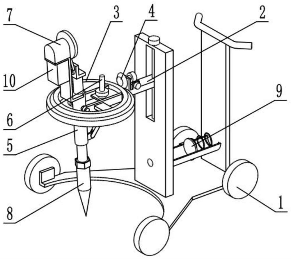
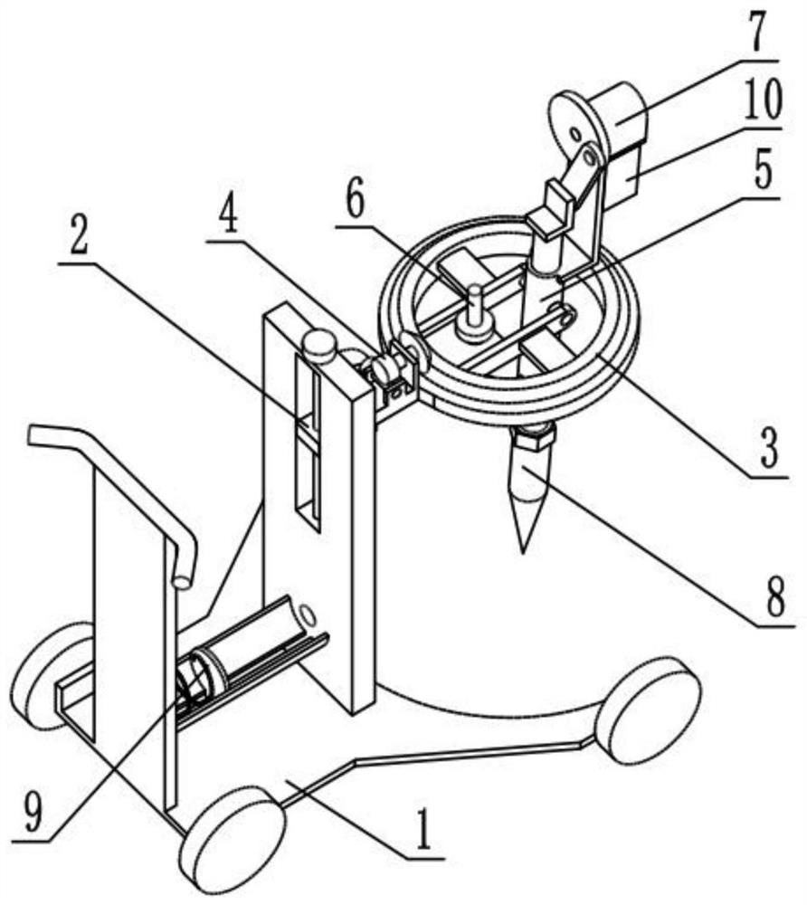
[0029] Such as Figure 1-11 Shown, a kind of ice surface punching device of fishpond comprises mobile frame 1, elevating mechanism 2, rotating frame 3, rotation adjustment mechanism 4, ice rod frame 5, ice angle adjustment mechanism 6, punching mechanism 7, ice Screw head 8, clamping mechanism 9 and mobile power supply 10, described elevating mechanism 2 is connected on the moving frame 1, and described rotating frame 3 and rotating adjusting mechanism 4 are all rotatably connected on the lifting mechanism 2, rotating frame 3 and The rotation adjustment mechanism 4 is connected by transmission, the ice rod frame 5 and the ice angle adjustment mechanism 6 are all rotatably connected on the rotation frame 3, the ice rod frame 5 and the ice angle adjustment mechanism 6 are rotatably connected, and the described opening The hole mechanism 7 is connected to the ice rod frame 5, the ice head 8 is screwed to the lower end of the punch mechanism 7, the clamping mechanism 9 is connecte...
specific Embodiment approach 2
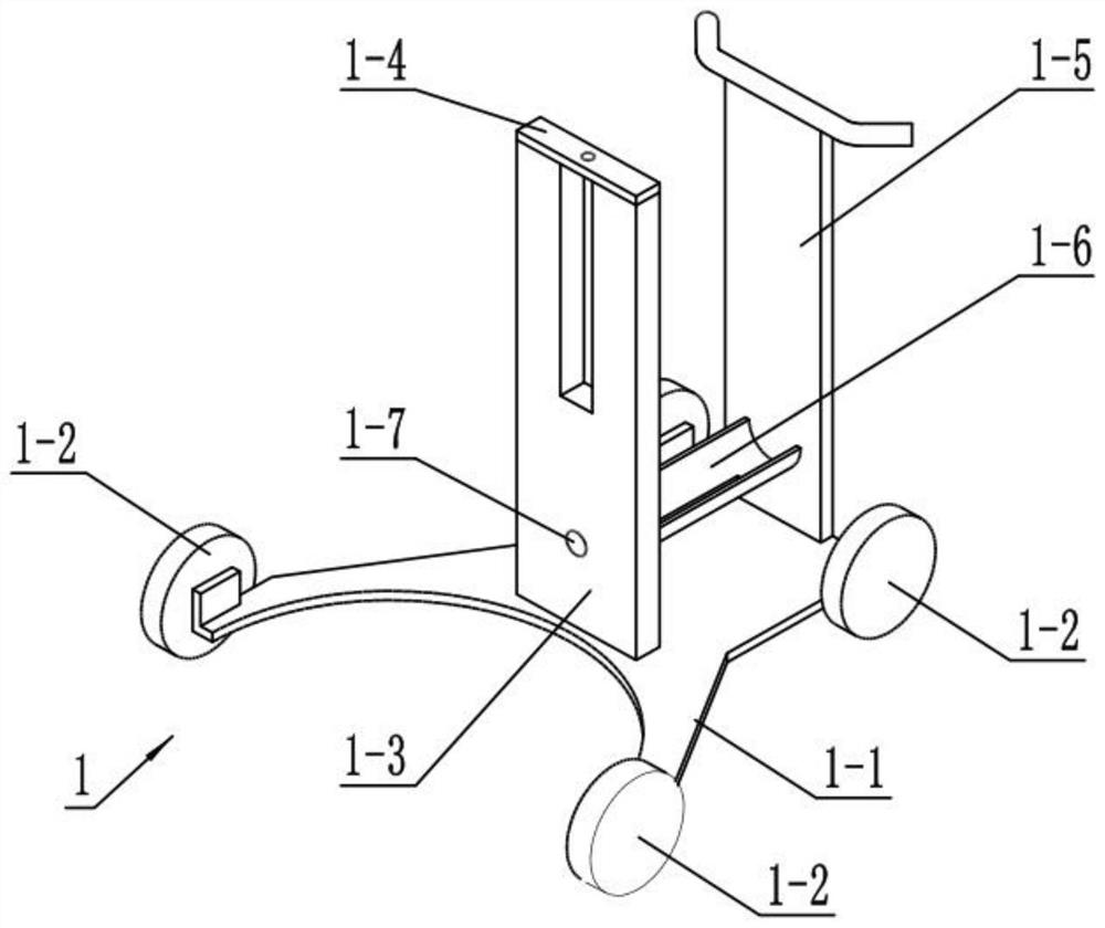
[0031] Such as Figure 1-11 As shown, the mobile frame 1 includes a base plate 1-1, a universal wheel 1-2, a support plate 1-3, an upper horizontal plate 1-4, an armrest frame 1-5, a semicircular pipe 1-6 and a positioning hole 1 -7, the front end of the bottom plate 1-1 is provided with a semicircular groove, and the four corners of the bottom plate 1-1 are all rotatably connected with universal wheels 1-2, and the four universal wheels 1-2 are all provided with self-locking devices, and the support plate 1-3 is fixedly connected to the base plate 1-1, the upper horizontal plate 1-4 is fixedly connected to the upper end of the support plate 1-3, the armrest frame 1-5 is fixedly connected to the rear end of the base plate 1-1, and the semicircular pipe 1-6 The front and rear ends of the armrest are respectively fixedly connected to the support plate 1-3 and the armrest frame 1-5, and the positioning holes 1-7 are arranged on the support plate 1-3;
[0032] The front end of th...
specific Embodiment approach 3
[0033] Such as Figure 1-11 As shown, the lifting mechanism 2 includes a lifting ring 2-1, an arm plate 2-2, an adjusting screw 2-3, a fixing plate I2-4 and a fixing plate II2-5, and the lifting ring 2-1 is fixedly connected At one end of the support arm plate 2-2, the adjusting screw 2-3 is screwed to the other end of the support arm plate 2-2, and there are two fixed plates I2-4, two fixed plates I2-4 and fixed plate II2 -5 are all fixedly connected on the support arm plate 2-2, the support arm plate 2-2 is slidingly connected in the support plate 1-3, and the adjusting screw rod 2-3 is rotatably connected to the upper horizontal plate 1-4;
[0034] Rotate the adjusting screw 2-3, and the arm plate 2-2 is raised and lowered on the adjusting screw 2-3 through thread transmission, and drives the lifting ring 2-1 to lift, thereby driving the rotating frame 3, the rotating adjusting mechanism 4, and the ice rod Frame 5, ice shovel angle adjustment mechanism 6, punching mechanis...
PUM
 Abstract
Description
Claims
Application Information
 - R&D
- Intellectual Property
- Life Sciences
- Materials
- Tech Scout
- Unparalleled Data Quality
- Higher Quality Content
- 60% Fewer Hallucinations
Browse by: Latest US Patents, China's latest patents, Technical Efficacy Thesaurus, Application Domain, Technology Topic, Popular Technical Reports.
© 2025 PatSnap. All rights reserved.Legal|Privacy policy|Modern Slavery Act Transparency Statement|Sitemap|About US| Contact US: help@patsnap.com


