
Welding tool for welding evaporation pipe

A technology for welding tooling and evaporating tubes, applied in welding equipment, auxiliary welding equipment, welding/cutting auxiliary equipment, etc., can solve the problems of general pipe clamping effect, inconvenience, inconvenient fixing of evaporating tubes, etc.

Pending Publication Date: 2022-04-19
CHINA HANGFA CHANGZHOU LANXIANG MACHINERY CO LTD
View PDF0 Cites 2 Cited by
  • Summary
  • Abstract
  • Description
  • Claims
  • Application Information

AI Technical Summary

Problems solved by technology

[0004] The purpose of the present invention is to solve the disadvantages in the prior art that the clamping effect of the traditional welding tool on the pipeline is general, it is inconvenient to fix the specific position of the evaporation tube, and it brings inconvenience to the operator, and a kind of evaporation tube is proposed. Welding Fixtures for Welding

Method used


Image

  • Welding tool for welding evaporation pipe
  • Welding tool for welding evaporation pipe
  • Welding tool for welding evaporation pipe

Examples


Embodiment 1

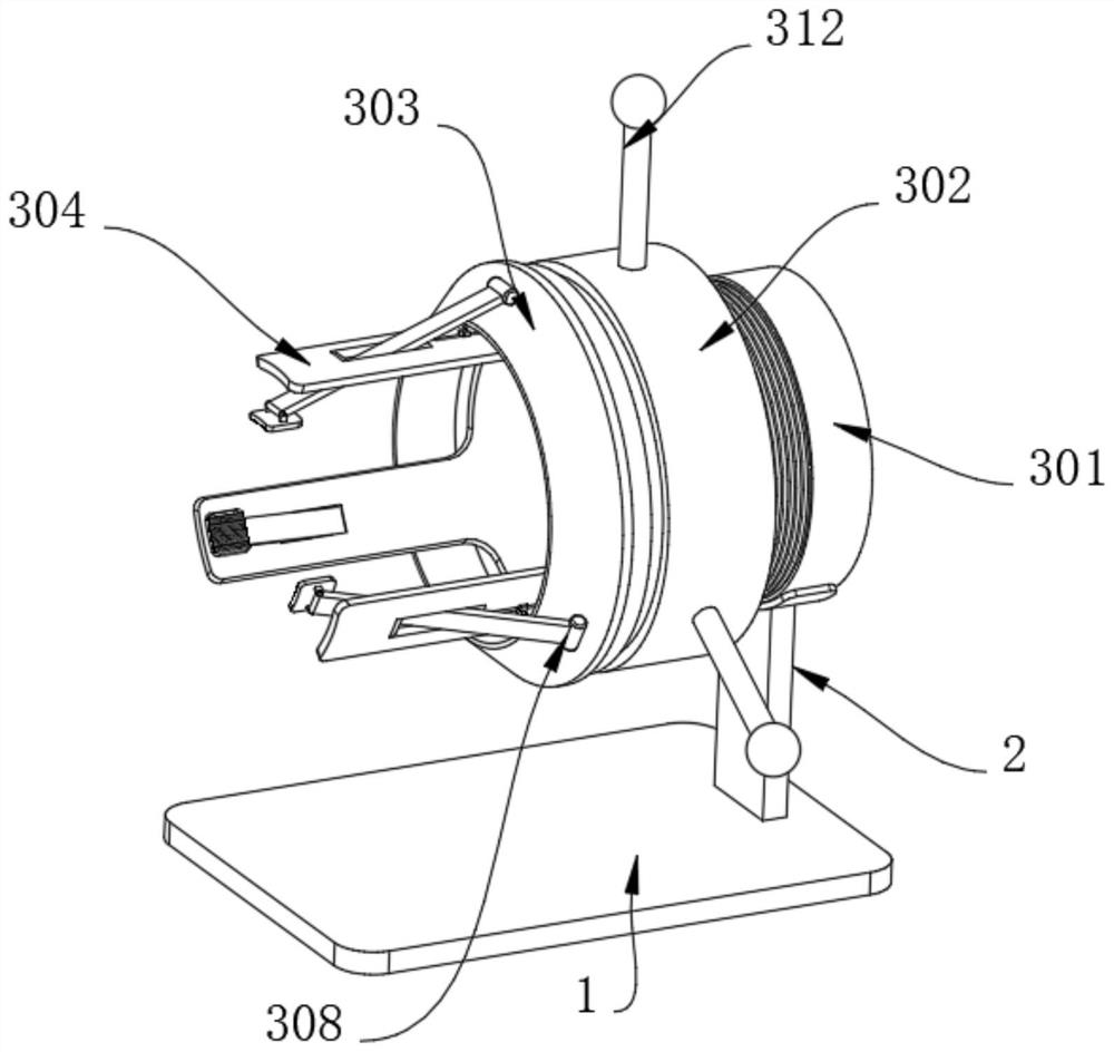
[0041] Example 1, such as Figure 1-8 As shown, the present invention provides a welding tool for evaporating tube welding, including two rectangular plates 1, a backing plate 408 and a clamping structure 3, the upper surfaces of the two rectangular plates 1 are fixedly connected with a support frame 2, and the support frame 2 A clamping structure 3 is provided at the end away from the rectangular plate 1, an adjusting structure 4 is provided at the side where the two rectangular plates 1 are close to each other, and a collecting structure 5 is provided on the upper surface of the backing plate 408.

[0042] The specific settings and functions of the clamping structure 3, the adjusting structure 4 and the collecting structure 5 will be described in detail below.

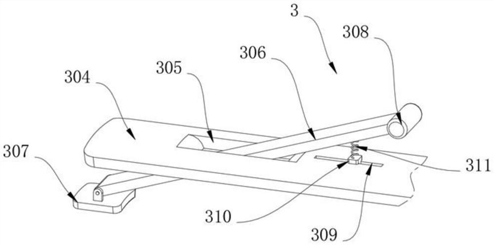
[0043] Such as image 3 and Figure 4 As shown, the clamping structure 3 includes a threaded pipe 301, which is fixedly connected to the upper end of the support frame 2, the circular arc surface of the threaded pi...

Embodiment 2

[0049]Embodiment 2, on the basis of Embodiment 1, the collection structure 5 includes a slide rail 51, the slide rail 51 is fixedly connected to the upper surface of the backing plate 408, the inner wall of the slide rail 51 is slidably connected with a limit bar 52, and the limit bar 52 is away from One side of the inner wall of the slide rail 51 is fixedly connected with a collection box 53, one side of the collection box 53 is fixedly connected with a handle 58, the side of the collection box 53 away from the handle 58 is connected with a slide plate 54, and both sides of the slide plate 54 are provided with slide holes 55. The inner wall of the sliding hole 55 of the sliding plate 54 is slidably connected with a scraper 56. When welding two evaporation tubes, it can cover and collect the waste generated by welding, and the collected waste can also be quickly transferred. , both ends of the scraper 56 are fixedly connected with an elastic rope 57, and the end of the elastic ...


PUM


Abstract

The invention provides a welding tool for evaporation pipe welding, and relates to the technical field of welding tools, the welding tool comprises two rectangular plates and a clamping structure, the upper surfaces of the two rectangular plates are fixedly connected with supporting frames, the clamping structure is arranged at the ends, away from the rectangular plates, of the supporting frames, and the clamping structure comprises a threaded pipe; the threaded pipe is fixedly connected to the upper end of the supporting frame, the arc surface of the threaded pipe is in threaded connection with a threaded ring, the arc surface of the threaded pipe is sleeved with an adjusting piece, three welding plates are evenly welded to one end of the threaded pipe, rectangular holes are formed in the arc surfaces of the welding plates, the corners of the two ends of the rectangular holes of the welding plates are subjected to round corner treatment, and the arc surfaces of the welding plates are connected with the threaded ring. The inner wall of the rectangular hole is rotationally connected with a rotating plate, and one end of the rotating plate is rotationally connected with a pressing block. According to the welding tool, the problems that the clamping effect of a traditional welding tool on a pipeline is common, the specific position of an evaporation pipe is inconvenient to fix, and inconvenience is brought to operators are solved.

Description

technical field [0001] The invention relates to the field of welding tooling technology, in particular to a welding tooling for evaporating tube welding. Background technique [0002] Welding tooling refers to the collective name of fixtures used to weld materials. With the development of the times, the structure and material of welding tooling have the characteristics of diversity. It is widely used in the field of plate processing and has the function of assisting processing personnel in welding. [0003] When welding the evaporator tube, it is necessary to use a welding tool to clamp and fix the evaporator tube, and then perform welding. However, the traditional welding tool has a general clamping effect on the tube, and it is inconvenient to fix the specific position of the evaporator tube, which is difficult for the operation. Inconvenience to staff. Contents of the invention [0004] The purpose of the present invention is to solve the disadvantages in the prior art...

Claims


Application Information

Patent Timeline
Patent Type & Authority Applications(China)
IPC IPC(8): B23K37/053B23K37/04B23K37/00B23K101/06
CPCB23K37/0533B23K37/0443B23K37/00B23K2101/06
Inventor 赵德乾
Owner CHINA HANGFA CHANGZHOU LANXIANG MACHINERY CO LTD
Learn More