Device for adjusting diameter of guide channel for bars

A technology for guiding channels and rods, which is applied in the field of size devices, and can solve problems such as the inability to maximize the guide surface of rods

Pending Publication Date: 2022-04-15
LNS管理责任有限公司
View PDF1 Cites 0 Cited by
  • Summary
  • Abstract
  • Description
  • Claims
  • Application Information

AI Technical Summary

Problems solved by technology

However, in both cases above, the geometry realized for the guide channel consists of a biconvex spherical lens, which always has the disadvantage of not being able to maximize the guide surface of the bar

Method used


Image

  • Device for adjusting diameter of guide channel for bars
  • Device for adjusting diameter of guide channel for bars
  • Device for adjusting diameter of guide channel for bars

Examples


Embodiment Construction

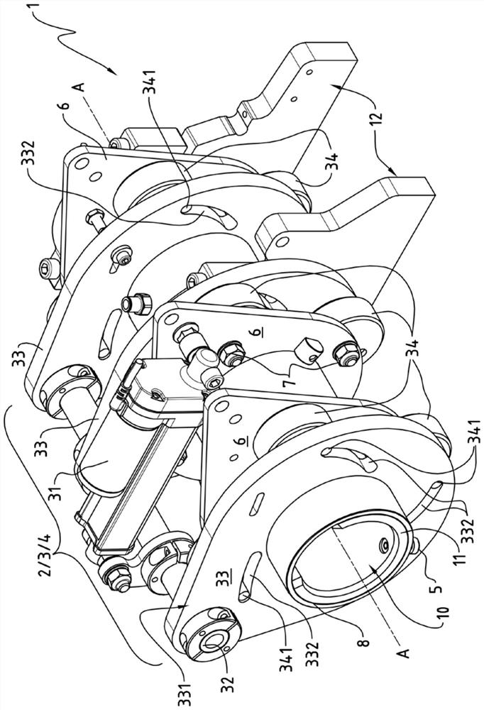
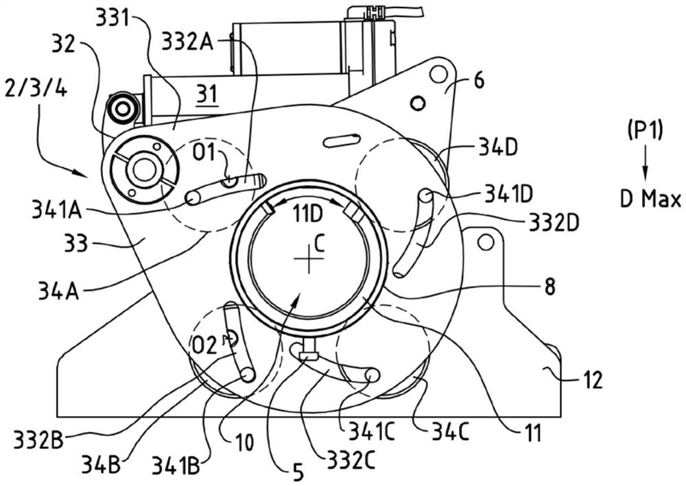
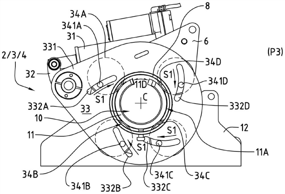
[0034] figure 1 Shows a perspective view of a bar feeder 1, here more specifically the bar feeder part equipped with a guide channel 10 according to a preferred embodiment of the invention, an adjustable guide element according to The guide channel is formed in sections by a one-piece flexible guide housing 11 made of, for example, polyurethane-based plastic or rubber material to dampen vibrations, and the guide The guide element is made integral with a cylindrical frame 8 similar to the front support by means of fixing pins 5 inserted in its bottom. In other words, the portion of the bar feeder shown in the Figures can itself be considered to constitute a front support.

[0035] The cylindrical frame 8 of the guide channel 10 is itself arranged on a base plate 12, here formed by several feet, and the means 2 for adjusting the diameter of the guide channel comprise together a clamping device 3 and a height adjustment device 4. The clamping device 3 acts on the flexible guide...


PUM


Abstract

The bar feeder (1) comprises a guide channel (10) centered on a constant guide axis (A-A), characterized in that the guide channel (10) is adjustable and is formed by an adjustable guide element which defines a guide channel having a constant centre (C) under the action of a device (2) which can be used to adjust the diameter of the guide channel, the guide channel is arranged such that the guide channel corresponds to a rod diameter comprised between a maximum rod diameter (DMax) at the first position (P1) and a minimum rod diameter (DMin) at the second position (P2).

Description

technical field [0001] The present invention relates to a device and a method for adjusting the dimensions of guide elements in, for example, a bar feeder for feeding the bars into a processing machine, usually a lathe. Background technique [0002] In the metallurgical industry, a bar feeder, also known as a bar loader, is a common device used to feed longer bars into processing machines such as automatic lathes. Thus, a continuous series of parts can be produced at the front end of the bar. [0003] A plurality of bars are fed into the automatic lathe through a bar feeder, which has a guide channel adapted to the diameter of the bar, and is usually equipped with a fixed bracket at its front end, usually referred to as a front bracket for short. The front bracket is the last guiding element that makes contact with the bar before it enters the lathe spindle and contains a through hole through which the bar passes in order to limit the vibration of the bar. The front bracke...

Claims


Application Information

Patent Timeline
Patent Type & Authority Applications(China)
IPC IPC(8): B23B13/02B23B13/08B23B13/12B23B31/163
CPCB23B13/08B23B13/123
Inventor K·维迪尔R·舍雷尔
Owner LNS管理责任有限公司
Why Eureka
Try Eureka