Ct method for the examination of a cyclically moving object

A periodic, moving technology, applied in the direction of radiological diagnostic instruments, applications, medical science, etc., can solve problems such as infeasibility, huge computing power, etc.

Inactive Publication Date: 2010-01-20
KONINK PHILIPS ELECTRONICS NV
View PDF7 Cites 0 Cited by
  • Summary
  • Abstract
  • Description
  • Claims
  • Application Information

AI Technical Summary

Problems solved by technology

In principle, they are used to reconstruct CT images with the least possible motion artifacts, but this method is currently not feasible because of the huge computing power required

Method used


Image

  • Ct method for the examination of a cyclically moving object
  • Ct method for the examination of a cyclically moving object
  • Ct method for the examination of a cyclically moving object

Examples


Embodiment Construction

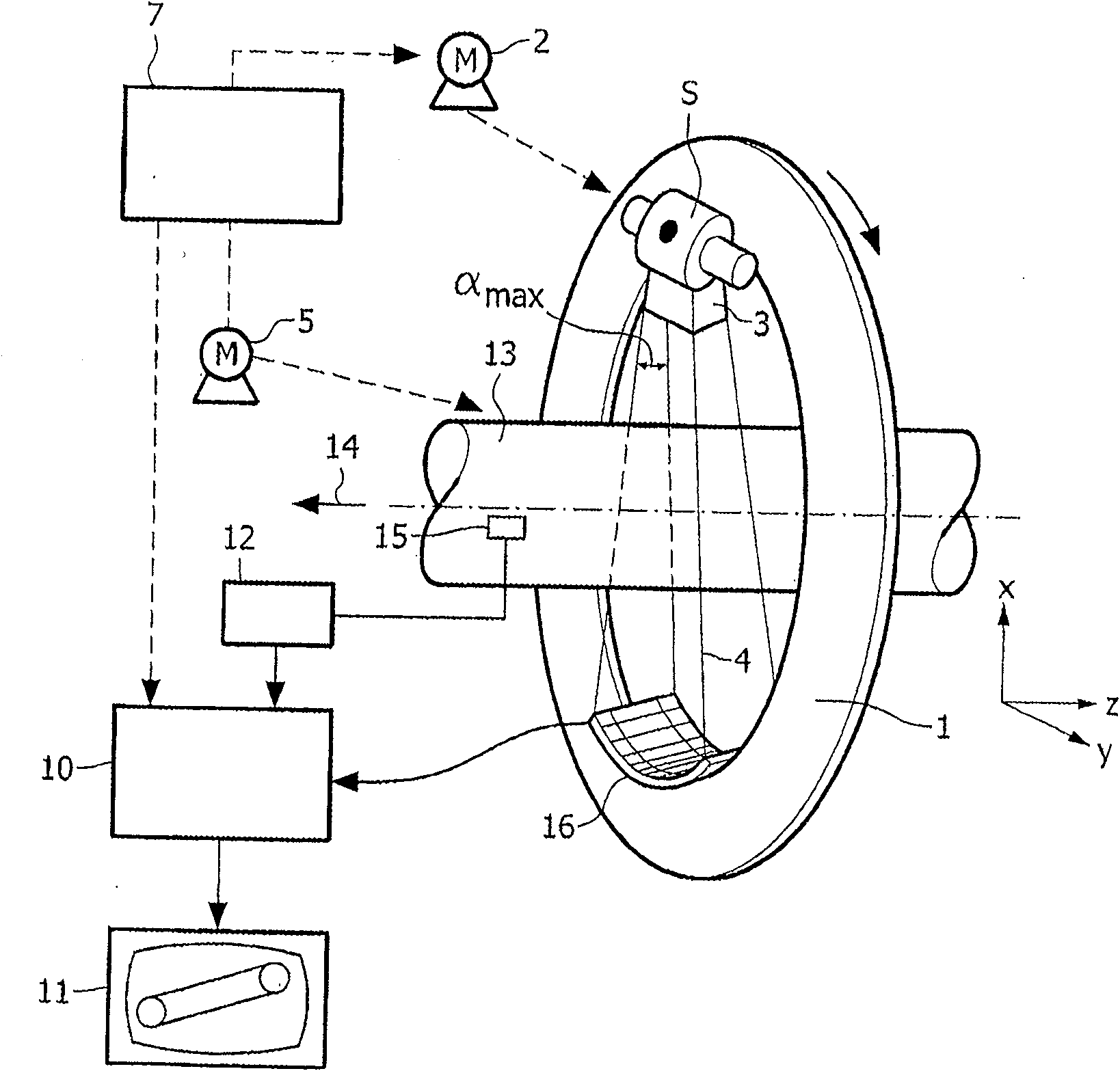
[0026] figure 1 The computed tomography apparatus represented in includes a gantry 1 that can rotate around a rotation axis 14 that is connected to figure 1 The z-direction of the x, y, z-coordinate system represented in is parallel. In addition, the gantry is driven by a motor 2 with a preferably constant but adjustable angular velocity. A radiation source S, such as an X-ray device, is fixed to the gantry. This is provided with a collimator arrangement 3 which forms a cone beam 4 from the radiation produced by the radiation source S, i.e. has A bundle of finite extensions other than zero.

[0027] The beam 4 penetrates an examination region 13, where an object such as a patient may be located on a patient examination platform (also not shown). The inspection zone 13 has a cylindrical shape. After passing through the examination zone 13, the X-ray beam strikes a two-dimensional detector unit 16 fixed to the gantry 1, which detector unit comprises a plurality of detector ...


PUM


Abstract

The invention relates to a computer tomography method for the detection of a cyclically moved object in an examination zone. First, after the acquisition of the measured values, a rough image of the examination zone is reconstructed from which a region relevant for the further method is selected. For the generation of an image with reduced motion artifacts or improved temporal resolution, reconstruction windows in predefinable position are used, which are optimized in such a way that they are, on the one hand, smallest possible, on the other hand, however, sufficiently large, to be able to reconstruct all voxels of this region. Only measured values acquired within the reconstruction windows are taken into account for the reconstruction of a CT image of the region.

Description

technical field [0001] The invention relates to a computed tomography method for detecting an examination region which is at least partially susceptible to periodic movements. Furthermore, the invention relates to a computed tomography apparatus for carrying out such a method, as well as a computer program for controlling such a computed tomography apparatus. Background technique [0002] During the examination of a periodically moving object, such as a patient's heart, it is disturbing to note that the time required for the radiation source of a computed tomography apparatus to rotate around the examination region is not negligibly short compared to the cardiac cycle. Therefore, if one tries to reconstruct a CT image of the heart (CT=computed tomography) from measurements acquired during a single rotation, this CT image will have strong motion artifacts, since the acquisition at different shift phases takes into account the Measurements. [0003] In order to reduce these ...

Claims


Application Information

Patent Timeline
Patent Type & Authority Patents(China)
IPC IPC(8): A61B6/03
CPCA61B6/541A61B6/4085A61B6/032
Inventor T·科勒M·格拉斯
Owner KONINK PHILIPS ELECTRONICS NV
Why Eureka
Try Eureka