Low-temperature vacuum radiation temperature parameter calibration system and calibration method

A technology of radiation temperature and low-temperature vacuum, applied in the field of low-temperature vacuum low-temperature vacuum radiation temperature parameter calibration system, can solve problems such as hidden dangers, difficult calibration of on-orbit space radiation temperature parameters, and inability to evaluate the accuracy of test data, so as to maintain consistency, Improving the calibration accuracy and designing a reasonable and ingenious effect

Pending Publication Date: 2022-04-15
BEIJING ZHENXING METROLOGY & TEST INST
View PDF6 Cites 1 Cited by
  • Summary
  • Abstract
  • Description
  • Claims
  • Application Information

AI Technical Summary

Problems solved by technology

[0005] Among the radiation temperature parameters, in addition to radiation temperature and radiation temperature uniformity, the calibration and traceability of NETD (noise equivalent temperature difference), MRTD (minimum resolvable temperature difference), and MDTD (minimum detectable temperature difference) are also important. The infrared load low temperature radiation temperature parameter test system can only test the radiation temperature, NETD (Noise Equivalent Temperature Difference), MRTD (Minimum Resolvable Temperature Difference), MDTD (Minimum Detectable Temperature Difference) test and even calibration traceability. The radiation temperature parameters in the orbital space are difficult to calibrate, and the accuracy of the test data cannot be evaluated, which makes the infrared load low-temperature infrared target detection performance test a hidden danger

Method used


Image

  • Low-temperature vacuum radiation temperature parameter calibration system and calibration method
  • Low-temperature vacuum radiation temperature parameter calibration system and calibration method
  • Low-temperature vacuum radiation temperature parameter calibration system and calibration method

Examples


Embodiment 1

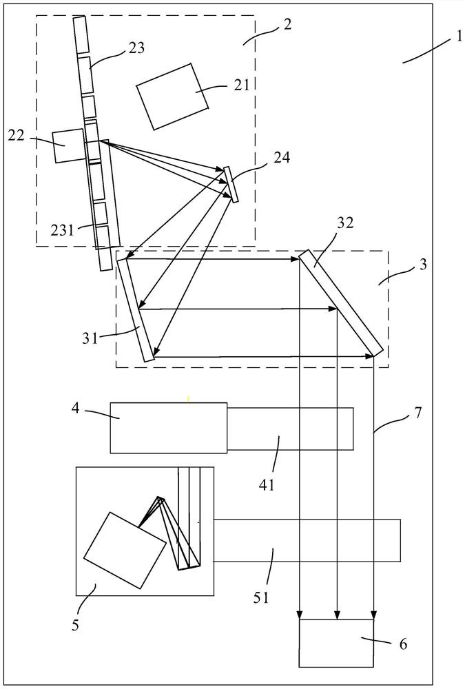
[0050] Example 1, see figure 1 , Figure 7 to Figure 10 According to an aspect of the present invention, an embodiment of the present invention provides a low-temperature vacuum radiation temperature parameter calibration system, including: a vacuum cooling chamber 1 for simulating a low-temperature vacuum environment;

[0051] An infrared temperature difference radiation emitting device 2, which is arranged in the vacuum cooling chamber 1, and is used to emit the first infrared radiation with a set temperature difference;

[0052] A collimating optical device 3, which is arranged in the vacuum cooling chamber 1 corresponding to the infrared temperature difference radiation emitting device 2, is used to receive the first infrared radiation and transmit the first infrared radiation to the target after collimation and processing The infrared load 6 is used for the target infrared load 6 to perform noise equivalent temperature difference calibration and / or minimum resolvable tem...


PUM


Abstract

The invention provides a low-temperature vacuum radiation temperature parameter calibration system and method, and the system comprises a vacuum cold cabin which is used for simulating a low-temperature vacuum environment; the infrared temperature difference radiation emission device is arranged in the vacuum cold cabin corresponding to the infrared temperature difference radiation emission device and is used for emitting first infrared radiation with a set temperature difference; and the collimation optical device is arranged in the vacuum cold cabin and is used for receiving the first infrared radiation, collimating the first infrared radiation and then transmitting the first infrared radiation to a target infrared load, so that noise equivalent temperature difference calibration and / or minimum distinguishable temperature difference calibration and / or minimum detectable temperature difference calibration are / is carried out on the target infrared load. The problems that radiation temperature parameters of an in-orbit space are difficult to calibrate, the accuracy of test data cannot be evaluated, and hidden dangers are generated in an infrared load low-temperature infrared target detection performance test are solved.

Description

technical field [0001] The invention relates to the technical field of infrared load calibration in orbital space, in particular to a low-temperature vacuum low-temperature vacuum radiation temperature parameter calibration system and a calibration method. Background technique [0002] Infrared payloads are infrared payload imagers. With the development of aerospace technology, the application of infrared payloads has been extended to near space and outer space. These systems include space reconnaissance systems, near space early warning systems, outer space infrared guidance strike systems, Anti-weapon systems, spaceborne infrared remote sensing systems, etc., with the gradual improvement of the technical and tactical performance requirements of these infrared payloads, calibration of radiation temperature parameters under low temperature and vacuum conditions has become an inevitable trend for the further development of target infrared payloads. [0003] For the applicatio...

Claims


Application Information

Patent Timeline
Patent Type & Authority Applications(China)
IPC IPC(8): G01J5/80G01J5/53
Inventor 邱超孙红胜王加朋吴柯萱翟思婷郭亚玭杜继东
Owner BEIJING ZHENXING METROLOGY & TEST INST
Why Eureka
Try Eureka