High-overload-resistant silicon sensing unit, micro-accelerometer and preparation method of high-overload-resistant silicon sensing unit
A sensitive unit, high overload technology, applied in the direction of measurement of acceleration, velocity/acceleration/shock measurement, microstructure device composed of deformable elements, etc., can solve the problem that the anti-overload performance of the micro accelerometer needs to be improved, and achieve improvement The effect of anti-overload performance, compression of production cycle and cost, and reduction of processing difficulty
- Summary
- Abstract
- Description
- Claims
- Application Information
AI Technical Summary
Problems solved by technology
Method used
Image

Examples
Embodiment 1
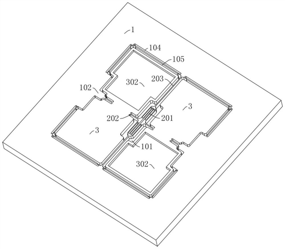
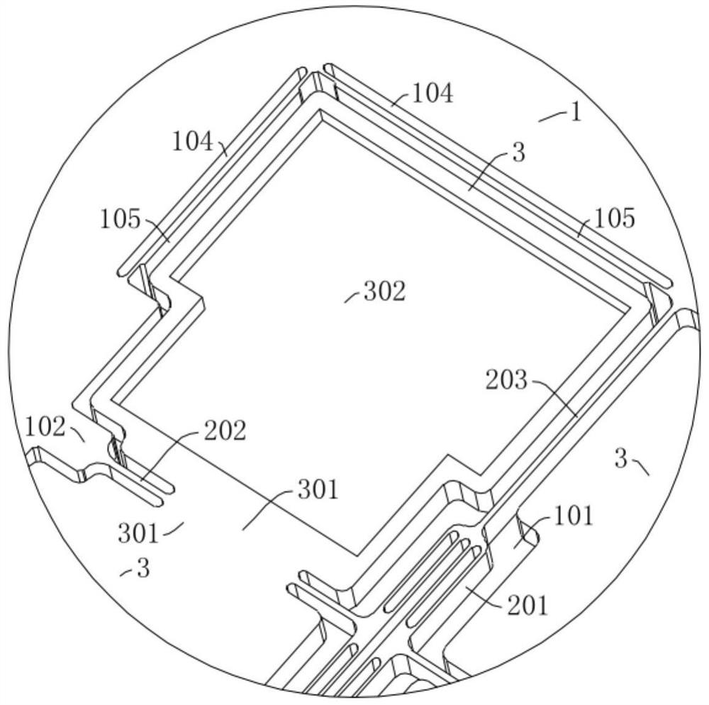
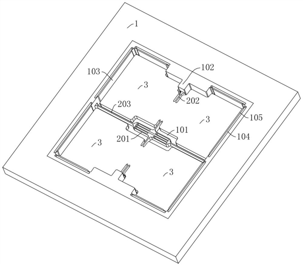
[0055] like Figure 1-3 Shown is an anti-high overload silicon sensor unit disclosed in this embodiment, which is mainly used in micro accelerometers. The sensitive unit includes an integrally formed outer frame 1 and a sensitive mechanism. The outer frame 1 is a square flat plate structure. The sensitive mechanism includes a composite beam structure and a mass assembly. The composite beam structure includes a beam stress release structure 201, a sensitive beam 202 and a displacement limiting beam. 203. The outer frame 1 has a hollow groove 101 , the hollow groove 101 is located in the middle area of the outer frame 1 , and the beam stress relief structure 201 is located in the center of the hollow groove 101 . Among them, the middle positions of the left and right sides of the beam stress relief structure 201 are respectively connected to the outer frame 1 through the sensitive beam 202, and the middle positions of the upper and lower ends of the beam stress relief structu...
Embodiment 2
[0066] like Figure 11-12 Shown is a micro-accelerometer disclosed in this embodiment, which includes a glass substrate 4 and the anti-high overload sensitive unit in Embodiment 1. The glass substrate 4 is provided with electrically connected pins and electrode assemblies. The whole of the glass substrate 4 is a square plate structure, and its overall size is larger than that of the outer frame 1 . The upper surface of the glass substrate 4 has a relief groove 401 corresponding to the position of the electrode assembly, leaving a space for arranging the electrode assembly. And the upper surface of the glass substrate 4 has two "door"-shaped bonding bosses 402 symmetrically along the relief groove 401. When the glass substrate 4 is connected, the lower surface of the outer frame 1 is used as the anchor point area, and the bonding bosses The platform 402 and the anchor area are connected and fixed by anodic bonding, which is not only mature and simple, but also easy to operate ...
Embodiment 3
[0072] like Figure 13 Shown is that this embodiment also discloses a preparation method of the micro-accelerometer in Embodiment 2, which specifically includes the following steps:
[0073] Step 1, prepare a thick silicon wafer and carry out calibration, cleaning and drying, namely Figure 13 as shown in (a);
[0074] Step 2, use thick glue to spread the glue on the lower surface of the silicon wafer, and develop the photolithographic pattern of the groove 103 on the bottom surface after photolithography, that is Figure 13 As shown in (b); the bottom groove 103 is etched by dry etching process, and the etching depth is the processing thickness from the lower surface of the silicon wafer to the lower surface of the sensitive mechanism, and then the silicon wafer is degummed, cleaned and dried processing, ie Figure 13 as shown in (c);
[0075] Step 3, use thick glue to spread the glue on the upper surface of the silicon wafer, and develop the photolithographic pattern of ...
PUM
 Abstract
Description
Claims
Application Information
 - Generate Ideas
- Intellectual Property
- Life Sciences
- Materials
- Tech Scout
- Unparalleled Data Quality
- Higher Quality Content
- 60% Fewer Hallucinations
Browse by: Latest US Patents, China's latest patents, Technical Efficacy Thesaurus, Application Domain, Technology Topic, Popular Technical Reports.
© 2025 PatSnap. All rights reserved.Legal|Privacy policy|Modern Slavery Act Transparency Statement|Sitemap|About US| Contact US: help@patsnap.com