Automatic welding mechanism for clothes rack panel

An automatic welding and clothing rack technology, applied in welding equipment, auxiliary welding equipment, welding/cutting auxiliary equipment, etc., can solve the problem of low processing efficiency, achieve the effect of improving welding efficiency and reducing blind spots

Pending Publication Date: 2022-04-15
REDMAN CORP
View PDF8 Cites 0 Cited by
  • Summary
  • Abstract
  • Description
  • Claims
  • Application Information

AI Technical Summary

Problems solved by technology

Due to the large number of panel welding nodes and the position of the side strips needs to be positioned at the design position, if the conventional manual welding method is used, the processing efficiency is low

Method used


Image

  • Automatic welding mechanism for clothes rack panel
  • Automatic welding mechanism for clothes rack panel
  • Automatic welding mechanism for clothes rack panel

Examples


Embodiment Construction

[0037] The following is attached Figure 2-7 The application is described in further detail.

[0038] The embodiment of the present application discloses an automatic welding mechanism for a garment rack panel.

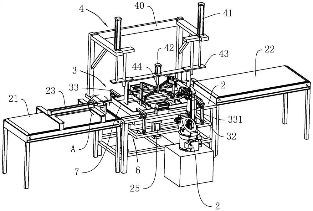
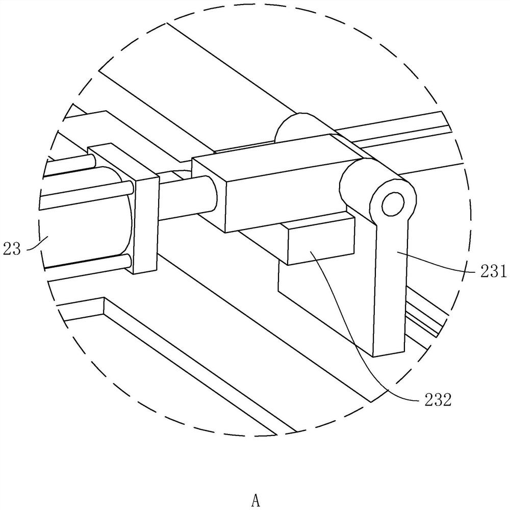
[0039] Such as figure 2 and image 3 , the automatic welding mechanism of the garment rack panel includes a welding robot 1 and a frame 2, the two sides of the frame 2 are respectively provided with a first conveyor 21 and a second conveyor 22, and the first conveyor 21 and the second conveyor 22 Transmission direction is identical and both adopt belt 651 machine, the belt 651 upper end surface of the first conveyor 21 is flush with frame 2, the belt 651 upper end surface of the second conveyor 22 is higher than frame 2, the first conveyor 21 An electric push rod 23 parallel to it is installed near one end of the frame 2, the drive end of the electric push rod 23 faces the frame 2 and is hinged with a push plate 231, and the bottom surface of the drive end of the ...


PUM


Abstract

The invention relates to an automatic welding mechanism for a clothes rack panel, and belongs to the field of clothes rack processing equipment, the automatic welding mechanism comprises a welding robot and a rack, a first conveyor and a second conveyor are respectively arranged on two sides of the rack, an electric push rod is arranged on the first conveyor, and a push plate is hinged to the driving end of the electric push rod; a stop block is arranged on the bottom face of the driving end of the electric push rod, the panel is placed on the rack, the rack is provided with a clamping assembly used for fixing the frame and an adjusting assembly used for positioning the edgings, a top plate moving in the height direction of the rack is slidably connected into the rack, a pushing air cylinder is arranged on the portion, below the top plate, of the rack, and a piston rod of the pushing air cylinder is connected with the top plate. A feeding assembly is arranged on the top plate, and a through groove allowing the top plate to stretch out is formed in the rack. The garment rack panel welding device has the effect of improving the garment rack panel welding machining efficiency.

Description

technical field [0001] The present application relates to the field of garment rack processing equipment, in particular to an automatic welding mechanism for garment rack panels. Background technique [0002] Clothing racks are used to display clothing, so that the clothing can be eye-catchingly displayed in front of the public, thereby increasing the role of advertising for products. At the same time, clothing racks with rich accessories can make each component can be installed flexibly, and then display products in an all-round way. Characteristics. [0003] Such as figure 1 , in actual production and processing, panels will be involved in the components of the clothing rack. The panel includes a frame 81 and two side bars 82, and the two side bars 82 are arranged in parallel in the frame 81. When assembling, it is necessary to check each side of the frame 81. Welding is performed between the corners and the side strips 82 and the frame 81 . Since there are many welding...

Claims


Application Information

Patent Timeline
Patent Type & Authority Applications(China)
IPC IPC(8): B23K37/00B23K37/04
Inventor 陆春蔡立荣丁建东徐国华
Owner REDMAN CORP
Why Eureka
Try Eureka