Special camera efficient cooling device applied to laser welding robot
A laser welding and cooling device technology, applied in laser welding equipment, welding equipment, metal processing equipment, etc., can solve the problems of damaging electrical components, reducing work efficiency, and low cooling efficiency, so as to reduce the probability of damage and improve the practical effect , to meet the effect of multi-directional demand
- Summary
- Abstract
- Description
- Claims
- Application Information
AI Technical Summary
Problems solved by technology
Method used
Image
Examples
Embodiment 1
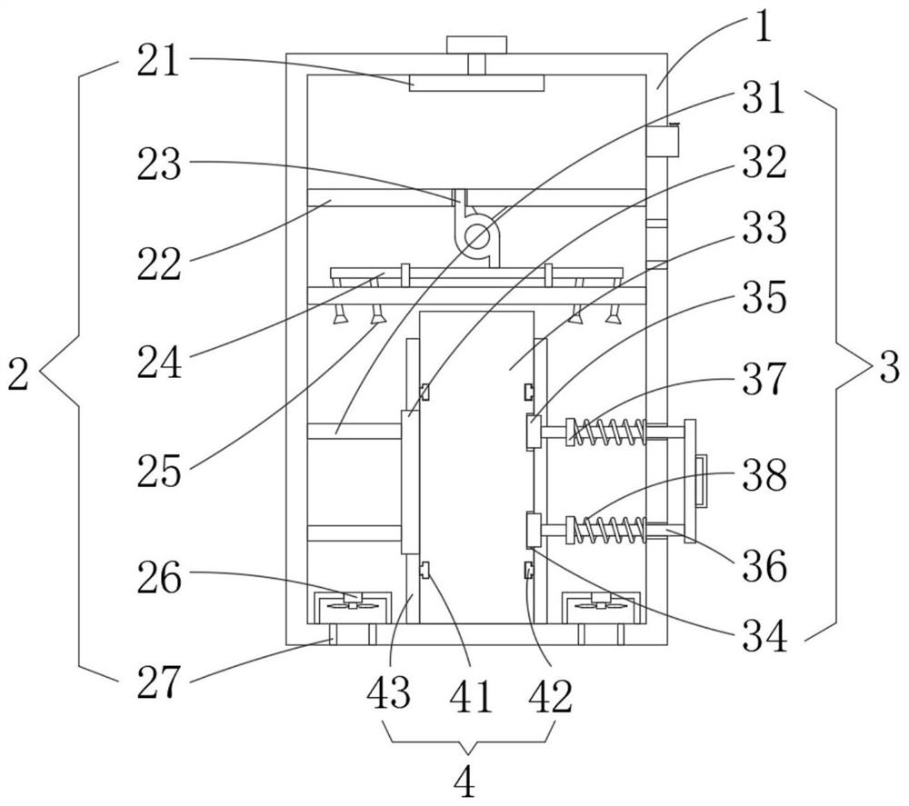
[0027] The present invention provides such Figure 1-2 As shown, a high-efficiency cooling device for cameras used in laser welding robots includes an installation box 1 and a cooling mechanism 2. The cooling mechanism 2 is arranged on the back of the inner cavity of the installation box 1, and the semiconductor cooling chip 21 in the cooling mechanism 2 is installed on the The back side of the inner cavity of the installation box 1 can be used to refrigerate the local position of the interior by using the semiconductor refrigeration sheet 21;
[0028] It is worth noting that, if figure 1 and 2 As shown, the cooling mechanism 2 also includes a partition 22, a fan 23, a delivery pipe 24, a nozzle 25, an exhaust fan 26 and a cooling hole 27, the partition 22 is installed on one side of the inner cavity of the installation box 1, and the fan 23 is installed on the partition On one side of 22, the conveying pipe 24 is communicated with the outlet end of the blower fan 23, and th...
Embodiment 2
[0032] see figure 2 , 5 And 6, the difference between present embodiment 2 and embodiment 1 is:
[0033] preferred, such as figure 2 , 5 As shown in and 6, the front portion of both sides of the inner chamber of the installation box 1 is provided with an installation mechanism 3, and the installation mechanism 3 includes a pole 31, a support plate 32, a camera body 33, a slot 34, an insert block 35, a connecting rod 36, a stopper Block 37 and spring 38, strut 31 are installed in the front part of one side of installation box 1 cavity, utilize the effect of strut 31 and support plate 32 to be used for assisting it to install, and can play the effect of auxiliary support to it.
[0034] Additionally, if figure 2 and 5 As shown, the support plate 32 is installed on one end of the support rod 31, the camera body 33 is placed at the bottom of the inner cavity of the installation box 1, the slot 34 is opened at the front and back of one side of the camera body 33, and the in...
Embodiment 3
[0040] see figure 1 , 3 And 4, the difference between this embodiment 3 and embodiment 1 and embodiment 2 is:
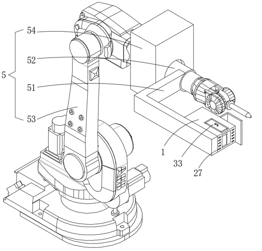
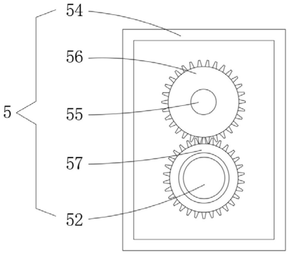
[0041] further, such as figure 1 , 3 As shown in and 4, one side of the installation box 1 is provided with an adjustment mechanism 5, and the adjustment mechanism 5 includes a connecting frame 51, a sleeve 52, a robot arm body 53, a connection box 54, a motor 55, a driving gear 56 and a driven gear 57 , The connecting frame 51 is installed on one side of the installation box 1, and the connecting frame 51 is used to conveniently connect the sleeve 52 so as to drive the installation box 1 to rotate.
[0042] Additionally, if figure 1 , 3 As shown in and 4, the sleeve pipe 52 is installed on one end of the connecting frame 51, the robot arm body 53 is movably installed on the inner wall of the sleeve pipe 52, the connection box 54 is installed on one side of the robot arm body 53 surface, and the motor 55 is installed on the connection The upper part of the box ...
PUM
 Abstract
Description
Claims
Application Information
 - Generate Ideas
- Intellectual Property
- Life Sciences
- Materials
- Tech Scout
- Unparalleled Data Quality
- Higher Quality Content
- 60% Fewer Hallucinations
Browse by: Latest US Patents, China's latest patents, Technical Efficacy Thesaurus, Application Domain, Technology Topic, Popular Technical Reports.
© 2025 PatSnap. All rights reserved.Legal|Privacy policy|Modern Slavery Act Transparency Statement|Sitemap|About US| Contact US: help@patsnap.com


