Powder falling control device and method for additive manufacturing

A technology of additive manufacturing and powder, which is applied in the direction of additive manufacturing, additive processing, chemical instruments and methods, etc. It can solve the problems of large space occupation, high precision requirements, and inability to implement powder addition, and achieves simple structure and controllability Strong, achieve the effect of directional deposition of powder

Active Publication Date: 2022-04-15
UNIV OF SCI & TECH BEIJING
View PDF9 Cites 1 Cited by
  • Summary
  • Abstract
  • Description
  • Claims
  • Application Information

AI Technical Summary

Problems solved by technology

Although the structure of the bottom powder feeding device is simple, it takes up a lot of space, and it is impossible to add powder during the printing process, while the upper powder feeding device takes up less space and is easy to realize automation
The current upward powder feeding equipment mainly relies on the rotation of the roller to control the falling powder. When the roller rotates, the powder in the silo moves along with the closed space formed by the toothed roller and the wall. However, the mechanism is complicated and the accuracy of the equipment is very high. , easy to wear, easy to leak powder or stick powder and other problems
In addition, CN109803775A describes a method of placing powder on the outside of a cylindrical net and letting the powder fall through the airflow to spread the powder. However, this method has complicated equipment and high precision requirements
There is also a powder laying method described in 10.1016 / j.cirp.2018.04.096. The base powder is laid by feeding the powder down, and then the powder is sucked away by the powder negative pressure absorption device, and then passed through a nozzle controlled by ultrasonic waves and micron tubes Shaped powder placer is used to place powder at fixed points, but it can only place micro-areas and form a miniature powder pile, and the laying efficiency is low

Method used


Image

  • Powder falling control device and method for additive manufacturing
  • Powder falling control device and method for additive manufacturing
  • Powder falling control device and method for additive manufacturing

Examples


Embodiment 1

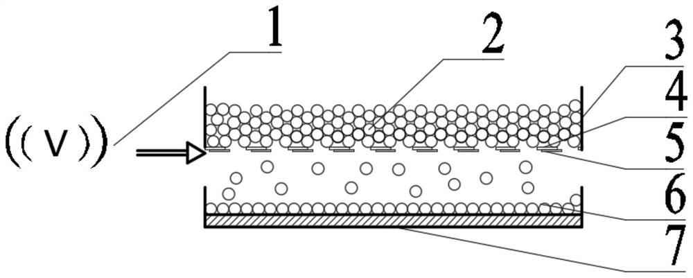
[0049] Such as figure 1 As shown, a device for controlling powder falling includes a powder outlet covered with a double-layer mesh screen (the first screen cloth 4 and the second screen cloth 5 ) and a screen cloth driving unit 8 .

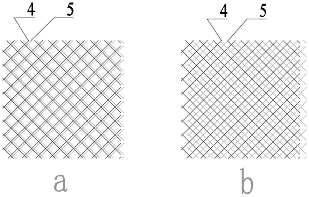
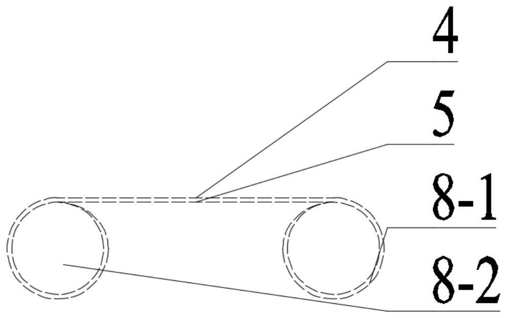
[0050] The device includes a powder outlet covered with double-layer screens 4 and 5, the double-layer screens 4 and 5 are attached and relatively movable, and the screens 4 and 5 have mesh holes. Such as figure 2 , image 3 As shown, the drive unit 8 can control the relative movement of the screens 4 and 5, thereby controlling the aperture size of the passing holes formed after the interference of the double-layer screens 4 and 5, thereby controlling the powder flow rate. In addition, in the feeding state, when the drive unit 8 moves the screens 4 and 5, the screen holes of the first screen 4 and the second screen 5 will overlap to form a channel (passing hole) with a larger aperture, and the powder Falls through the channel and deposits on ...

Embodiment 2

[0061] On the basis of Example 1, such as Figure 4 As shown, a controlled powder drop device for additive manufacturing includes a moving mechanism, a vibration unit 1, and a powder storage bin 9, an intermediate bin 10, and double-layer screens 4, 5 arranged in sequence from top to bottom.

[0062] The device is arranged on a moving mechanism and can move along a set path.

[0063] The powder storage bin 9 is arranged at the top for storing the powder to be placed. The intermediate bin 10 is connected to the lower part of the powder storage bin 9 for maintaining the stability of the powder below. The double-layer screens 4, 5 are placed at the opening below the intermediate bin 10 through the fixing unit 11, and the screen driving device 8 is connected to the double-layer screens 4, 5 to control the flow of powder.

[0064] Preferably, the whole powder storage bin 9 can be in the shape of a funnel or other shapes with an open top and an open bottom.

[0065] Preferably, t...

Embodiment 3

[0072] A device capable of directional deposition, on the basis of embodiment 2, comprising a template;

[0073] A template is introduced outside the second screen 5 to control the pattern of powder laying. The template can be a board with square holes or other patterns.

[0074] The movement of the template can also be controlled to control the orientation of the powder laying, so that the directional deposition of the powder can be further realized. Through the combination of multiple above-mentioned devices, each device controls the deposition of different powders at different positions, thereby realizing multi-material powder laying.

[0075] Compared with the existing equipment, the device of the present invention has simple structure, strong controllability, can control the powder feeding speed, is especially used for the control of fine powder, and can control the powder laying conveniently and efficiently.


PUM


Abstract

The invention relates to the technical field of powder metallurgy, and provides a powder falling control device and method for additive manufacturing. The device comprises a powder storage bin, a middle bin, a double-layer screen and a screen driving unit; the middle bin is arranged at the lower end of the powder storage bin to keep the stability of powder below the powder storage bin; the double-layer screen is arranged at a powder outlet in the bottom of the middle bin; the double-layer screen cloth is attached to each other, relative displacement parallel to the screen cloth face can be generated between the double-layer screen cloth, interference is generated between the double-layer screen cloth, the sizes of through holes of the double-layer screen cloth are changed, and then the falling amount of powder is controlled. And the screen driving unit controls the relative displacement between the double-layer screens. The powder falling control method comprises the steps of calibration, powder falling start and stop control and powder falling rate control. Compared with existing equipment, the device is simple in structure and high in controllability, the powder feeding speed can be controlled, the device can be particularly used for controlling fine powder, powder laying can be conveniently and efficiently controlled, and the device has wide application prospects.

Description

technical field [0001] The invention relates to the technical field of powder metallurgy, in particular to a powder drop control device and method for additive manufacturing. Background technique [0002] With the development of the times, the additive manufacturing technology based on the principle of discrete accumulation fully meets the needs of large-scale personalized customization in the future society with its powerful personalized manufacturing capabilities, and subverts the traditional design of high-end equipment with its strong support for design innovation. And manufacturing approaches, forming unprecedented new solutions, revolutionizing a large number of product concepts, and helping my country's manufacturing industry transform from transformation to innovation-driven development model. [0003] Among them, powder bed-based additive manufacturing has the advantages of high precision, no need for other supports, and less powder waste, so it is widely used. In p...

Claims


Application Information

Patent Timeline
Patent Type & Authority Applications(China)
IPC IPC(8): B07B9/00B07B1/28B22F1/14B22F10/73B33Y10/00B33Y40/00
CPCY02P10/25
Inventor 张百成张梓浩温耀杰李祺祺郭朝阳曲选辉
Owner UNIV OF SCI & TECH BEIJING
Why Eureka
Try Eureka