
Boost conversion circuit, device and method

A conversion circuit and boost control technology, applied in the output power conversion device, the conversion of DC power input to DC power output, photovoltaic power generation and other directions, can solve the problem of insufficient boost capacity of the boost converter.

Pending Publication Date: 2022-04-12
SHENZHEN POWER SUPPLY BUREAU
View PDF6 Cites 0 Cited by
  • Summary
  • Abstract
  • Description
  • Claims
  • Application Information

AI Technical Summary

Problems solved by technology

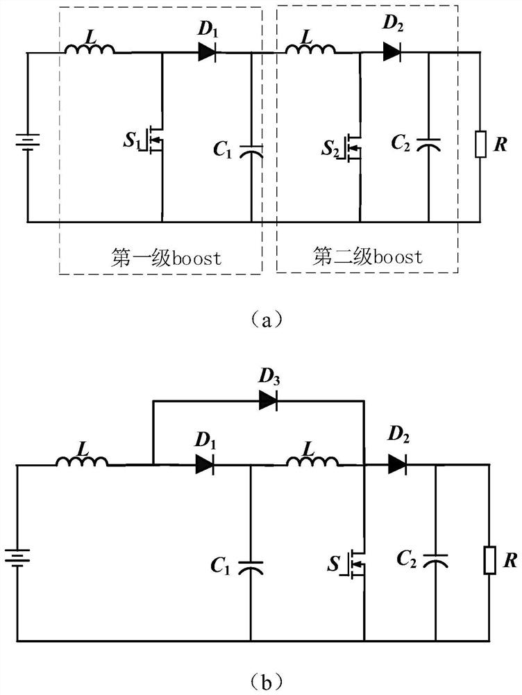
[0004] Based on this, it is necessary to provide a boost conversion circuit, device and method for the above technical problems to solve the problem of insufficient boosting capacity of traditional boost converters

Method used


Image

  • Boost conversion circuit, device and method
  • Boost conversion circuit, device and method
  • Boost conversion circuit, device and method

Examples


Embodiment Construction

[0048] In order to facilitate the understanding of the present application, the present application will be described more fully below with reference to the relevant drawings. Embodiments of the application are given in the drawings. However, the present application can be embodied in many different forms and is not limited to the embodiments described herein. On the contrary, the purpose of providing these embodiments is to make the disclosure of this application more thorough and comprehensive.

[0049] Unless otherwise defined, all technical and scientific terms used herein have the same meaning as commonly understood by one of ordinary skill in the technical field to which this application belongs. The terms used herein in the specification of the application are only for the purpose of describing specific embodiments, and are not intended to limit the application.

[0050] It can be understood that the terms "first", "second" and the like used in this application may be...


PUM


Abstract

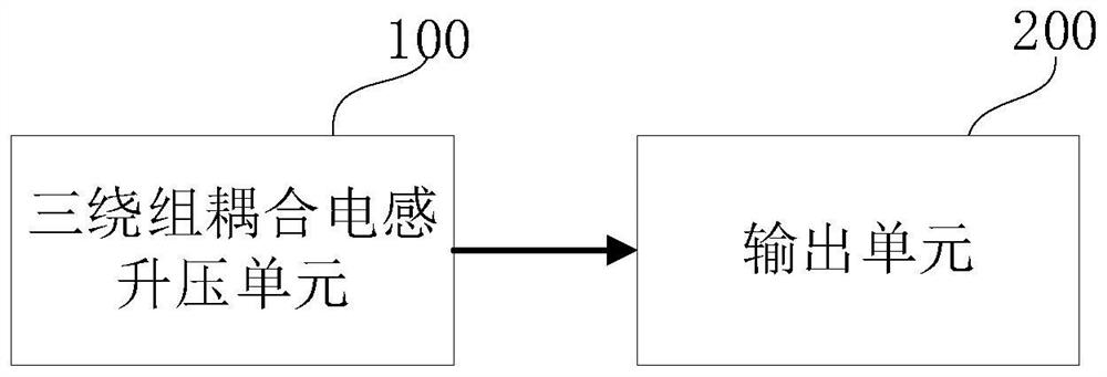
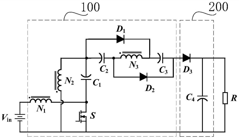
The invention relates to a boost conversion circuit, which comprises a three-winding coupling inductance boost unit and an output unit, and is characterized in that the three-winding coupling inductance boost unit is used for controlling a controllable switch unit in the three-winding coupling inductance boost unit to act according to a boost control signal so as to boost the voltage of a standby power supply of a power grid to a first voltage of a preset voltage value; and the output unit is connected with the three-winding coupling inductance boosting unit and is used for generating stable second voltage according to the first voltage. According to the boost conversion circuit, the three-winding coupling inductor is arranged, the parameter turn ratio is introduced for the boost conversion circuit, high gain can be achieved by adjusting the turn ratio, meanwhile, the limit duty ratio is avoided, in addition, the leakage inductance of the three-winding coupling inductor can restrain the reverse recovery problem of the output diode, and the output voltage of the boost conversion circuit is improved. In addition, in the boost conversion circuit, the controllable switch unit can realize zero-voltage switching, so that the switching loss of the switch tube is reduced, and the efficiency of the conversion circuit is improved.

Description

technical field [0001] The present application relates to the technical field of DC-DC conversion, in particular to a boost conversion circuit, device and method. Background technique [0002] High-gain DC-DC (DC-DC) converters are widely used in industrial production and life. For example, in uninterruptible power supply systems, the low output voltage of lead-acid batteries needs to be boosted to a high voltage of 380V for inverters. Busbar, in the photovoltaic grid-connected power generation system, the output voltage of the photovoltaic array is low, but the DC busbar voltage of the power supply network is high. At this time, a high-gain DC-DC converter is required for boost conversion. [0003] The traditional boost converter has a boost function, and its gain is 1 / (1-D), where D is the duty cycle of the converter. In theory, a boost converter can be used to obtain a high voltage gain, but in practical applications , due to the existence of the equivalent series resist...

Claims


Application Information

Patent Timeline
IPC IPC(8): H02M3/156
CPCY02E10/56Y02B70/10
Inventor 柴二亮陈泰霖杜光键符湛茹王京杨兴驰何明
Owner SHENZHEN POWER SUPPLY BUREAU
Learn More