Water stop device for starting slurry shield glass fiber enclosure structure

A glass fiber and enclosure structure technology, applied in shaft equipment, shaft lining, tunnel lining, etc., can solve the problems of easy cutting to the curtain, leakage of the door, failure of the water-stop structure, etc., and achieve the effect of saving manpower, material resources and time.

Pending Publication Date: 2022-04-12
TENGDA CONSTR GROUP CORP
View PDF1 Cites 0 Cited by
  • Summary
  • Abstract
  • Description
  • Claims
  • Application Information

AI Technical Summary

Problems solved by technology

However, in this water-stop structure, when the shield machine cuts the glass fiber enclosure structure, it is easy to cut the cord, resulting in the failure of the water-stop structure, resulting in a high risk of shield initiation, which is prone to water leakage, sand leakage, etc. danger

Method used


Image

  • Water stop device for starting slurry shield glass fiber enclosure structure
  • Water stop device for starting slurry shield glass fiber enclosure structure
  • Water stop device for starting slurry shield glass fiber enclosure structure

Examples


Embodiment 1

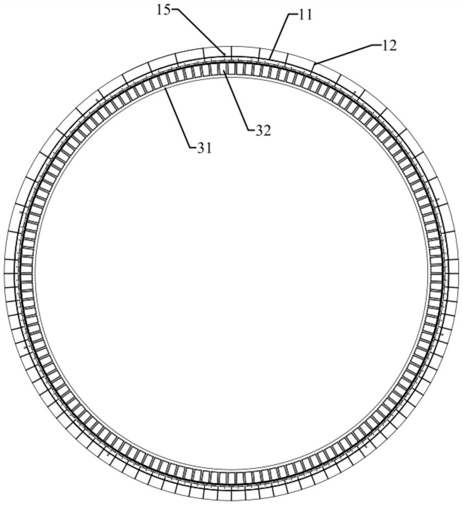
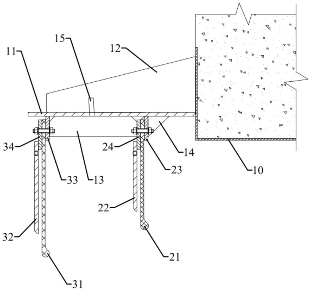
[0046] see figure 1 and figure 2 , The embodiment of the present invention provides a water-stop device for the initiation of mud-water shield glass fiber enclosure structure, including a box body 11, a first water-stop structure, a second water-stop structure and a sealing door structure.

[0047]The box body 11 is arranged on the outside of the hole, and one end of the box body 11 is fixedly connected with the steel ring 10 of the hole. Generally, a steel ring 10 is pre-embedded in the side wall of the shield well, and the steel ring 10 plays a certain supporting role. In this embodiment, the axis of the box 11 coincides with the axis of the steel ring 10. When the shield machine 30 starts, the starting axis of the shield machine 30 coincides with the axis of the box 11, that is, it starts along the straight line of the hole.

[0048] Both the first water stop structure and the second water stop structure are arranged inside the box body 11, the first water stop structure...

Embodiment 2

[0073] Figure 8 Embodiment 2 is shown, in which components identical or corresponding to those in Embodiment 1 are identified with reference numerals corresponding to Embodiment 1. For simplicity, only the differences between Embodiment 2 and Embodiment 1 are described. The difference is that the axis of the box 11 and the axis of the steel ring 10 are set at an angle. Since the starting axis of the shield machine 30 coincides with the axis of the box 11, the axis of the shield machine 30 and the steel ring There is an included angle between the axes of 10, the shield machine 30 starts along the curve, the shield machine 30 advances, passes through the box body 11 and the steel ring 10 and enters the hole in turn.

[0074] Wherein, the box body 11 can be welded by several arc plates during manufacture, and the width of the arc plates along the axial direction is gradually changed. In this embodiment, the box body 11 is welded by four arc plates.

[0075] By adjusting the s...


PUM


Abstract

The invention discloses a water stop device for starting of a slurry shield glass fiber enclosure structure, and belongs to the technical field of tunnel construction, the water stop device comprises a box body, a first water stop structure and a second water stop structure, the box body is annularly arranged on the outer side of a tunnel portal, and one end of the box body is fixedly connected with a steel ring of the tunnel portal; the first water stop structure is arranged on the inner side of the box body, the first water stop structure comprises first curtain cloth which is annularly arranged and a plurality of first turning plates which are arranged on the outer side of the first curtain cloth, and the first curtain cloth and the steel rings are arranged at intervals; the second water stop structure is arranged on the inner side of the box body and located on the outer side of the first water stop structure, the second water stop structure comprises second curtain cloth arranged annularly and a plurality of second turning plates arranged on the outer side of the second curtain cloth, and the width of the first curtain cloth in the radial direction is smaller than that of the second curtain cloth in the radial direction. Due to the fact that the first curtain cloth and the steel rings are arranged at intervals, and the radial width of the first curtain cloth is smaller than that of the second curtain cloth, the first curtain cloth cannot be damaged when the shield tunneling machine cuts the glass fiber enclosure structure.

Description

technical field [0001] The invention relates to the technical field of tunnel construction, in particular to a water stop device used for the initiation of mud-water shield glass fiber enclosure structures. Background technique [0002] With the rapid development of society, tunnel projects such as urban subways, highways, and railways are becoming more and more common. Among the many methods of urban tunnel construction, the shield method is characterized by its fast construction speed, high safety, and small impact on the surrounding environment. Advantages are widely used in tunnel construction. [0003] The construction of the shield method is generally divided into three stages, namely, shield initiation, normal excavation, and reception. The start of the shield machine is a key link in the construction of the tunnel shield method, and it is also one of the difficulties in the construction of the shield method. Its construction effect has an important impact on the qua...

Claims


Application Information

Patent Timeline
Patent Type & Authority Applications(China)
IPC IPC(8): E21D11/38E21D11/15E21D11/10E21D9/08
Inventor 王兴龙张轶姬铭蔡柏松胡娅红
Owner TENGDA CONSTR GROUP CORP
Why Eureka
Try Eureka