
Self-adjusting deceleration strip

A speed bump, self-adjusting technology, used in springs/shock absorbers, vibration suppression adjustment, roads, etc., can solve problems such as affecting the riding experience, suspension impact force, and large costs, to ensure normal traffic, reduce Impact force, damage reduction effect

Inactive Publication Date: 2022-04-12
张应堂
View PDF0 Cites 0 Cited by
  • Summary
  • Abstract
  • Description
  • Claims
  • Application Information

AI Technical Summary

Problems solved by technology

[0003] Although the speed reduction belt has a good speed control ability, the vehicle will inevitably produce larger bumps when passing the speed reduction belt, which will affect the riding experience. It will have a large impact on the suspension and cause damage to the suspension. Secondly, sometimes in order to ensure the speed limit of the vehicle, multiple sets of speed reduction belts will be set in succession. At this time, the vehicle speed is slow and it is easy to stop the vehicle. The owner needs to refuel the pedal to cross, and the operation is relatively troublesome
[0004] Furthermore, the deceleration belt achieves deceleration by protruding from the ground, and cannot distinguish the passing objects. In many cases, under the condition of not speeding, it can only reflect the role of obstacles and affect the normal passage of some people, such as tricycles, wheelchairs, etc., may need to It takes a lot of effort to get over

Method used


Image

  • Self-adjusting deceleration strip
  • Self-adjusting deceleration strip
  • Self-adjusting deceleration strip

Examples


Embodiment Construction

[0021] The following will clearly and completely describe the technical solutions in the embodiments of the present invention with reference to the accompanying drawings in the embodiments of the present invention. Obviously, the described embodiments are only some, not all, embodiments of the present invention. Based on the embodiments of the present invention, all other embodiments obtained by persons of ordinary skill in the art without making creative efforts belong to the protection scope of the present invention.

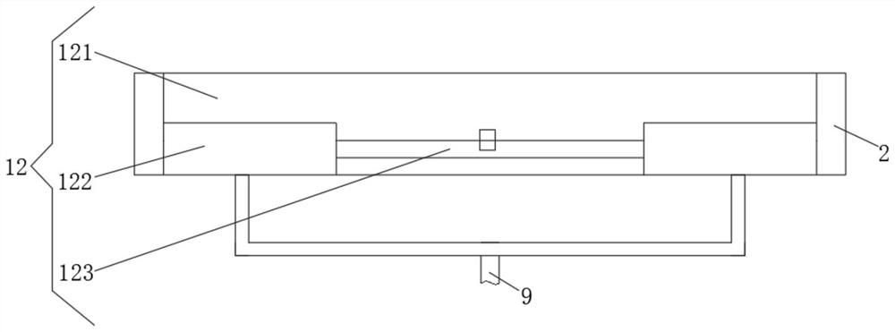
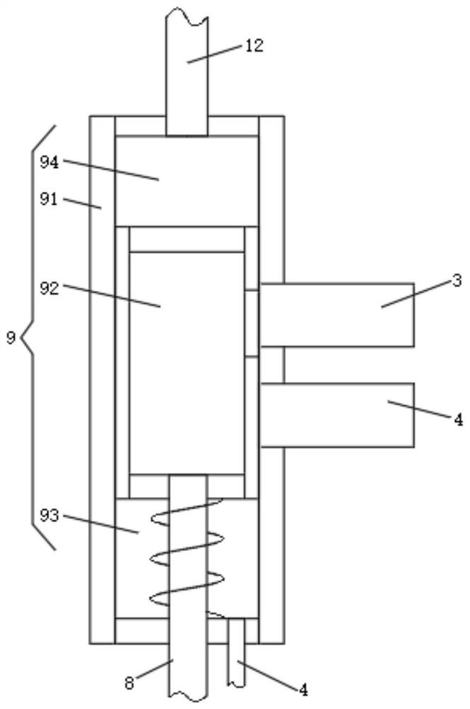
[0022] see figure 1 , a self-adjusting speed bump, including a box body 1 buried under the ground. The box body 1 is a cuboid similar to the road width. At the upper end, the bottom of the briquetting block 2 is connected with the first hydraulic cylinder 3 and the second hydraulic cylinder 4, and the first hydraulic cylinder 3 and the second hydraulic cylinder 4 are connected in series, that is, the first hydraulic cylinder 3 and the second hydraulic cylinder...


PUM


Abstract

The invention relates to the technical field of road equipment, and discloses a self-adjusting deceleration strip which comprises a box body buried underground, the upper end of the box body is movably connected with a pressing block, the bottom of the pressing block is connected with a first hydraulic cylinder and a second hydraulic cylinder, and the first hydraulic cylinder and the second hydraulic cylinder are connected in series. The self-adjusting deceleration strip rarely protrudes out of the ground and can be compressed normally, when a vehicle passes by at a low speed, the vehicle cannot jolt, impact force received by the vehicle is reduced, damage is reduced, when the vehicle passes by at a high speed, the self-adjusting deceleration strip rarely protrudes out of the ground and cannot be compressed, the vehicle can be effectively prevented from traveling together, and the deceleration effect is achieved; the front wheel is detected firstly, the action of the rear wheel is determined according to the speed of the front wheel, and when the vehicle runs normally, the vehicle is hardly influenced, namely, under most conditions, obstacles are not reflected, and normal passing of normal pedestrians or vehicles is guaranteed.

Description

technical field [0001] The invention relates to the technical field of road equipment, in particular to a self-adjusting speed bump. Background technique [0002] Speed ​​bumps are common equipment in daily life. Speed ​​bumps are installed at the entrances of some units with a large flow of people and close to the road to control the speed of passing vehicles and avoid traffic accidents. [0003] Although the speed reduction belt has a good speed control ability, the vehicle will inevitably produce larger bumps when passing the speed reduction belt, which will affect the riding experience. It will have a large impact on the suspension and cause damage to the suspension. Secondly, sometimes in order to ensure the speed limit of the vehicle, multiple sets of speed reduction belts will be set in succession. At this time, the vehicle speed is slow and it is easy to stop the vehicle. The owner needs to refuel the pedal to cross, and the operation is relatively troublesome. [...

Claims


Application Information

Patent Timeline
Patent Type & Authority Applications(China)
IPC IPC(8): E01F9/529F16F15/023
Inventor 张应堂
Owner 张应堂
Learn More