
Hopper of concrete mixing plant

A mixing plant and concrete technology, which is applied in mixing plants, clay preparation devices, mixing operation control, etc., can solve the problems of low concrete mixing efficiency, short service life of mixing equipment, and lack of uniform distribution, so as to improve the preparation efficiency and quality. The effect of reducing uneven raw material mass and reducing stirring time

Inactive Publication Date: 2022-04-12
王巧
View PDF0 Cites 1 Cited by
  • Summary
  • Abstract
  • Description
  • Claims
  • Application Information

AI Technical Summary

Problems solved by technology

[0002] In various modern construction projects, concrete is widely used, and the preparation methods of concrete are various, usually including the preparation and mixing of concrete raw materials such as sand aggregate, cement and some additives, and the two-stage mixing process. Among them, there are various mixing methods for concrete. There are two types of forced type and self-falling type. According to the different types of concrete, it can also be divided into two types: dry mixing and wet mixing. In small-scale concrete mixing projects, it is usually completed by manual participation. In large-scale concrete preparation projects, concrete They are all uniformly stirred and distributed by the mixing station to improve efficiency. The proportion before mixing in the mixing station is often directly loaded into the mixer using the quantitative weighing and distribution system of the mixing station. Adding various concrete raw materials, because the raw materials directly added to the mixing drum have not been pretreated, it will cause a large area of ​​separation between the concrete configuration water and other raw materials, and often not evenly distributed, resulting in a long time for the mixer to fully mix. , resulting in low mixing efficiency for concrete preparation and short service life of mixing equipment

Method used


Image

  • Hopper of concrete mixing plant
  • Hopper of concrete mixing plant
  • Hopper of concrete mixing plant

Examples


Embodiment Construction

[0018] The technical solutions in the embodiments of the present invention will be clearly and completely described below in conjunction with the accompanying drawings in the embodiments of the present invention. Obviously, the described embodiments are only some of the embodiments of the present invention, not all of them. Based on The embodiments of the present invention and all other embodiments obtained by persons of ordinary skill in the art without making creative efforts belong to the protection scope of the present invention.

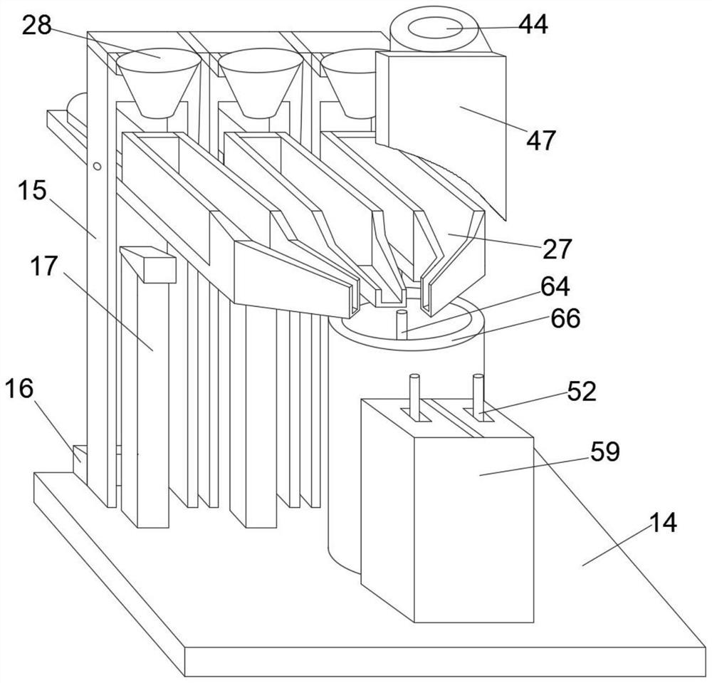
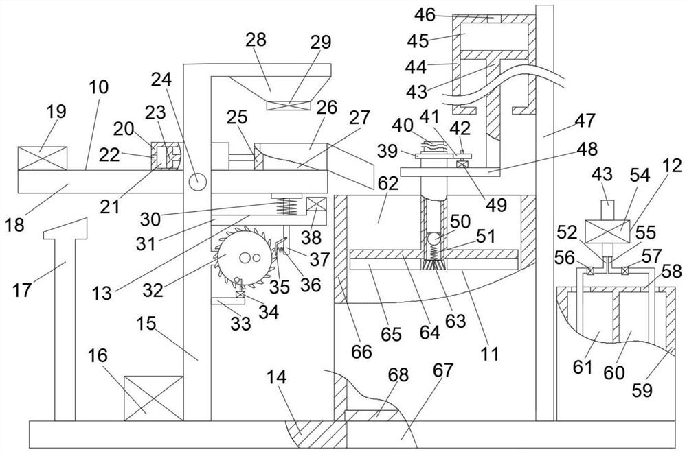
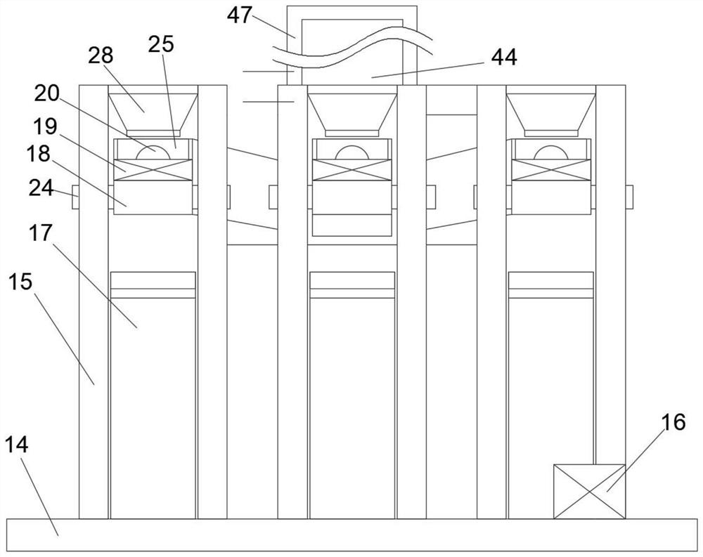
[0019] refer to Figure 1-Figure 7 , the present invention provides a concrete mixing plant hopper, comprising a base 14, six batching main boards 15 uniformly distributed front and rear are fixedly connected to the upper end of the base 14, and the six batching main boards 15 are divided into three groups front and rear, and two of each group A storage bin 28 is fixedly connected between the two batching main boards 15, the lower end of the sto...


PUM


Abstract

The concrete mixing plant hopper comprises a base, the upper end face of the base is fixedly connected with a hydraulic pump, a mixing main plate, a water tank and a mixing barrel, the upper end face of the base is fixedly connected with three limiting frames which are evenly distributed front and back, a discharging port is formed in the base, the upper end face of the base is fixedly connected with a telescopic air pump, and the telescopic air pump is fixedly connected with a telescopic sleeve. The upper end of the batching main plate is fixedly connected with a batching rotating shaft, the batching rotating shaft is rotationally connected with a batching mechanism, the right end face of the batching main plate is fixedly connected with a proportion adjusting mechanism, and the left end face of the modulation main plate is fixedly connected with a modulation mechanism. A water supply mechanism is arranged above a water tank fixedly connected with the upper end face of the base. The device can replace most functions of a weighing system of a mixing station, water and other concrete raw materials are uniformly mixed in a layered manner, the occurrence of raw material clusters which are not uniformly mixed with the water is reduced, the mixing time of a concrete mixer is shortened, and the concrete preparation efficiency and quality are improved.

Description

technical field [0001] The present application relates to the field of concrete preparation, in particular to a hopper of a concrete mixing station. Background technique [0002] In various modern construction projects, concrete is widely used, and the preparation methods of concrete are various, usually including the preparation and mixing of concrete raw materials such as sand aggregate, cement and some additives, and the two-stage mixing process. Among them, there are various mixing methods for concrete. There are two types of forced type and self-falling type. According to the different types of concrete, it can also be divided into two types: dry mixing and wet mixing. In small-scale concrete mixing projects, it is usually completed by manual participation. In large-scale concrete preparation projects, concrete They are all uniformly stirred and distributed by the mixing station to improve efficiency. The proportion before mixing in the mixing station is often directly ...

Claims


Application Information

Patent Timeline
Patent Type & Authority Applications(China)
IPC IPC(8): B28C9/02B28C7/04B28C7/12
Inventor 王巧
Owner 王巧
Learn More