Handheld machine tool and handheld electric tool with same
A technology of hand-held machine tools and tools, which is applied in the field of hand-held electric tools and hand-held machine tools. It can solve the problems that the tool head cannot match the head of the same machine tool, which cannot be realized, and increases the cost of production and living, so as to achieve flexible storage and transportation. Changeable, small footprint, easy to store or transport
- Summary
- Abstract
- Description
- Claims
- Application Information
AI Technical Summary
Problems solved by technology
Method used
Image
Examples
Embodiment 1
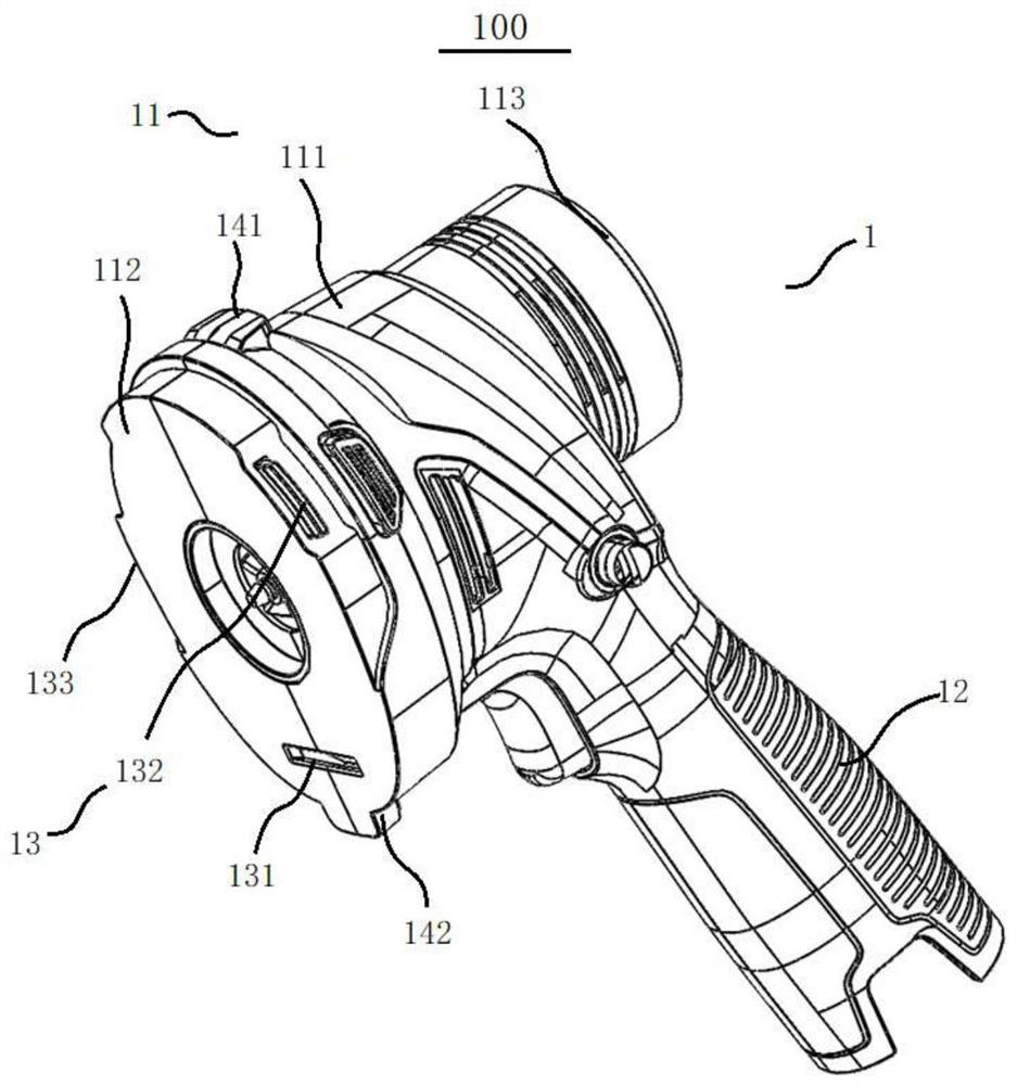
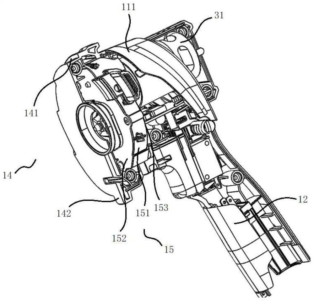
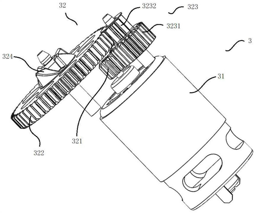
[0044] In order to solve the problems in the prior art, the present invention provides a Figure 1 to Figure 4 The hand-held machine tool 100 shown includes a main body housing 1, a driving device 3 arranged in the main body housing 1, and the main body housing 1 is provided with Figure 5 to Figure 7 or Figure 8 to Figure 12 The tool head mounting part 11 of the shown tool head 200 is form-locked and / or force-locked; When the tool head 200 is installed on the tool head mounting part 11, the tool head 200 can realize form-locking and / or force-locking connection by means of the first mounting component 13 and the first locking component 21, so that the driving device 3 can be connected with a first Maximum torsional strength to drive the tool head 200 to work;
[0045] When the tool head 200 including the second locking assembly 22 is installed on the tool head mounting part 11, the tool head 200 can realize form-locking and / or force-locking connection by means of the second...
Embodiment 2
[0073] Specifically, in the above-mentioned embodiment 1, only the implementation manner in which the first locking assembly 21 is set on the tool head 200 is introduced. Two embodiments of the locking assembly 22.
[0074] Specifically, such as Figure 1 to Figure 4 As shown, the hand-held power tool 100 includes a main body housing 1 and a driving device 3 located in the main body housing 1. The main body housing 1 includes an operating handle 12 extending toward one end of the main body housing 1 for holding and a The other end of the housing 1 extends a tool head mounting portion 11 . The tool head mounting portion 11 includes a first side plate 111 and a first top plate 112 and a first bottom plate 113 disposed at two ends of the first side plate 111 . Preferably, the first side panel 111 is a curved surface.
[0075] Specifically, the tool head installation part 11 is used to install such as Figure 8 to Figure 12 As shown in the tool head 200, the first mounting ass...
Embodiment 3
[0096] Further, in the above-mentioned embodiment 1 and embodiment 2, only one locking assembly is provided on the tool head 200. In other feasible solutions, the first locking assembly 21 and the second locking assembly can also be provided on the tool head 200 at the same time. Components 22 , and selectively engage with the first mounting component 13 through the first locking component 21 , and be locked with the second mounting component 14 through the second locking component 22 . Therefore, when two kinds of locking components are provided on the tool head 200 , an adapted connection mode can be selected based on the force on the tool head 200 itself, so as to achieve a stable connection between the tool head 200 and the hand-held power tool 100 .
[0097] It can be understood that when the first locking component 21 and the second locking component 22 are arranged on the same tool head 200 at the same time, each structure of the first locking component 21 and each struc...
PUM
 Abstract
Description
Claims
Application Information
 - R&D Engineer
- R&D Manager
- IP Professional
- Industry Leading Data Capabilities
- Powerful AI technology
- Patent DNA Extraction
Browse by: Latest US Patents, China's latest patents, Technical Efficacy Thesaurus, Application Domain, Technology Topic, Popular Technical Reports.
© 2024 PatSnap. All rights reserved.Legal|Privacy policy|Modern Slavery Act Transparency Statement|Sitemap|About US| Contact US: help@patsnap.com


