
Numerical control machine tool cooling liquid filtering device

A filter device, CNC machine tool technology, applied in metal processing machinery parts, maintenance and safety accessories, metal processing equipment, etc., can solve problems such as easy blockage of drainage pipes, inability to use coolant directly, waste of resources, etc.

Inactive Publication Date: 2022-04-12
张连志
View PDF0 Cites 1 Cited by
  • Summary
  • Abstract
  • Description
  • Claims
  • Application Information

AI Technical Summary

Problems solved by technology

Generally divided into metal cutting machine tools, forging machine tools and woodworking machine tools, etc. During the processing of iron parts, various machine tools used in machining workshops will generate a large amount of iron filings, which will remain in the machining coolant In the process of machine tool equipment, a large amount of dust, solid particle pollutants and other sundries will be mixed into the cooling liquid during the working process. The cooling liquid used in the operation of the existing machine tool is generally discharged directly to the outside, wasting resources, and After the coolant is recovered, it cannot be used directly. Impurities in the coolant can easily block the drain pipe, and the recovered coolant needs to be processed

Method used


Image

  • Numerical control machine tool cooling liquid filtering device
  • Numerical control machine tool cooling liquid filtering device
  • Numerical control machine tool cooling liquid filtering device

Examples


Embodiment Construction

[0027] The following will clearly and completely describe the technical solutions in the embodiments of the present invention with reference to the accompanying drawings in the embodiments of the present invention. Obviously, the described embodiments are only some, not all, embodiments of the present invention. Based on the embodiments of the present invention, all other embodiments obtained by persons of ordinary skill in the art without creative efforts fall within the protection scope of the present invention.

[0028] In describing the present invention, it is to be understood that the terms "opening", "upper", "lower", "thickness", "top", "middle", "length", "inner", "surrounding" etc. Indicating orientation or positional relationship is only for the convenience of describing the present invention and simplifying the description, and does not indicate or imply that the components or elements referred to must have a specific orientation, be constructed and operated in a sp...


PUM


Abstract

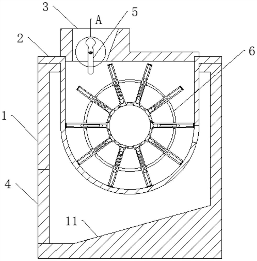
The invention discloses a numerical control machine tool cooling liquid filtering device, and relates to the technical field of numerical control machine tools. The device comprises an outer shell, a feeding part is installed in the outer shell, an end cover is installed on an end opening of the feeding part in a matched mode, a slag discharging opening communicated with the interior of the outer shell is formed in the side edge of the feeding part, a feeding opening communicated with the interior of the feeding part is formed in the end cover, an outlet is formed in the bottom of the outer shell, and a door body is installed in the outlet. A filtering part is installed in the feeding part, and the outlet end of the filtering part sequentially penetrates through the feeding part and the outer shell to be communicated with the exterior of the outer shell. Cooling liquid carrying a large amount of impurities pushes the installed filtering part to rotate, the impurities falling between the two adjacent side plates are pushed by the side plates to move towards one side of the slag discharging opening, and due to the fact that the position of the slag discharging opening is lower than the position of the axis of the filtering part, the impurities moving to the slag discharging opening are separated from the slag discharging opening under the action of gravity. And the cooling liquid enters the outer shell through the slag discharging opening, and primary separation of impurities in the cooling liquid is achieved.

Description

technical field [0001] The invention belongs to the technical field of numerical control machine tools, and in particular relates to a cooling liquid filter device for numerical control machine tools. Background technique [0002] A machine tool refers to a machine that manufactures a machine, also known as a machine tool or a tool machine, and is customarily referred to as a machine tool. Generally divided into metal cutting machine tools, forging machine tools and woodworking machine tools, etc. During the processing of iron parts, various machine tools used in machining workshops will generate a large amount of iron filings, which will remain in the machining coolant In the process of machine tool equipment, a large amount of dust, solid particle pollutants and other sundries will be mixed into the coolant during the working process. The coolant used in the operation of the existing machine tool is generally discharged directly to the outside, wasting resources, and Afte...

Claims


Application Information

Patent Timeline
Patent Type & Authority Applications(China)
IPC IPC(8): B23Q11/10B23Q11/00
Inventor 张连志
Owner 张连志
Learn More