A high-pressure nozzle device, degumming unit and degumming machine
A high-pressure nozzle and nozzle technology, applied in the direction of injection device, injection device, electrical components, etc., can solve the problem that glue and metal cannot be effectively peeled off, and achieve the effect of high pressure, small area and small pressure
- Summary
- Abstract
- Description
- Claims
- Application Information
AI Technical Summary
Problems solved by technology
Method used
Image
Examples
no. 1 example
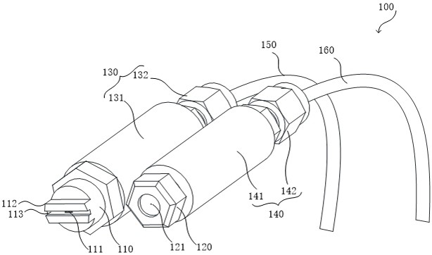
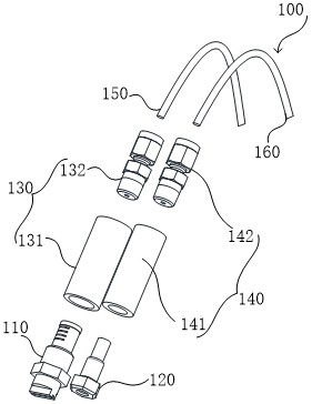
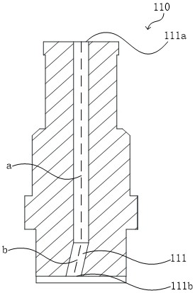
[0043] see Figure 1-4 , which is a high-pressure nozzle assembly 100 provided in the first embodiment of the present invention. The high pressure nozzle assembly 100 includes a slit nozzle 110 and a columnar nozzle 120 . Wherein, the slit-shaped nozzle 110 includes: a slit-shaped opening section 111 and a slit-shaped spray cavity section communicating with it, and the slit-shaped opening section 111 and the slit-shaped spray cavity section are located in the slit-shaped nozzle 110; The axis b of the slot-shaped opening section 111 is inclined to the axis a of the slot-shaped spray chamber section; the columnar nozzle 120 includes; The columnar spray chamber segment is located in the columnar nozzle 120, and the axis d of the columnar opening segment 121 is arranged in parallel with the axis c of the columnar spray chamber segment; wherein, the axis a of the slit-shaped spray chamber segment and the columnar spray chamber The axes c of the cavity segments are arranged in par...
no. 2 example
[0054] see Figure 7 , which is a schematic structural diagram of a high-pressure nozzle device 230 provided by the second embodiment of the present invention. The high-pressure nozzle device 230 includes, for example, a nozzle fixing member 240 , a scanning arm 250 , a rotating assembly 270 , a driving assembly 280 and the high-pressure nozzle assembly 100 provided in the first embodiment. For example, the nozzle fixing member 240 is connected to the high pressure nozzle assembly 100; the scanning arm 250 is connected to the nozzle fixing member 240; the rotating assembly 270 is connected to the end of the scanning arm 250 away from the nozzle fixing member 240; Assembly 280 may rotate and / or raise and lower rotating assembly 270 .
[0055] Preferably, the nozzle holder 240 is provided with a first side and a second side that are perpendicular to each other. The first side is provided with a first fixing hole 241 and a second fixing hole 242, the first fixing hole 241 is sl...
no. 3 example
[0064] see Figure 9 , which is a schematic structural diagram of a degumming unit 200 provided by the third embodiment of the present invention. The degumming unit 200 includes, for example, a degumming cavity housing 210 , a wafer mounting position 220 , and the high-pressure nozzle device 230 provided in the second embodiment.
[0065] Preferably, the degumming chamber housing 210 is provided with a degumming working space 213, the wafer mounting position 220 is located in the degumming working space 213 and is connected to the bottom plate 211 of the degumming chamber casing 210, and the high-pressure nozzle device 230 is connected to the The bottom plate 211 of the glue chamber housing 210 is located on one side of the wafer mounting position 220 .
[0066] Specifically, see Figure 10 , the bottom surface of the degumming chamber shell 210 is provided with a perforation, and the rotating shaft 273 passes through the perforation, so that the drive assembly 280 is locate...
PUM
 Abstract
Description
Claims
Application Information
 - R&D
- Intellectual Property
- Life Sciences
- Materials
- Tech Scout
- Unparalleled Data Quality
- Higher Quality Content
- 60% Fewer Hallucinations
Browse by: Latest US Patents, China's latest patents, Technical Efficacy Thesaurus, Application Domain, Technology Topic, Popular Technical Reports.
© 2025 PatSnap. All rights reserved.Legal|Privacy policy|Modern Slavery Act Transparency Statement|Sitemap|About US| Contact US: help@patsnap.com


