A multi-beam polarized oct imaging device and imaging method thereof

An imaging device and multi-beam technology, applied in the field of optical imaging, can solve the problems of small scanning field of view, slow running speed, single measurement performance, etc., and achieve the effect of improving lateral resolution, imaging depth and resolution.

Active Publication Date: 2022-05-13
PEKING UNIV +1
View PDF15 Cites 0 Cited by
  • Summary
  • Abstract
  • Description
  • Claims
  • Application Information

AI Technical Summary

Problems solved by technology

[0004] In order to overcome the problems of single measurement performance, slow running speed and small scanning field of view in current OCT measuring instruments, the present invention proposes a multi-beam polarized OCT imaging device and its imaging method

Method used


Image

  • A multi-beam polarized oct imaging device and imaging method thereof
  • A multi-beam polarized oct imaging device and imaging method thereof
  • A multi-beam polarized oct imaging device and imaging method thereof

Examples


Embodiment 1

[0062] In this embodiment, the samples are outer skin, cerebral cortex, and cornea, etc. There is no lens-like medium between the sample to be imaged and the imaging lens, and a focusing imaging lens is selected; at this time, the corresponding samples of different sample arm branches are in At different positions in the horizontal direction, the beam penetration depth of each sample arm branch is the same, and the optical path difference between each sample arm branch and the reference arm is different; different sample arm branches correspond to different OCT interference signal frequency segments , do not cross each other.

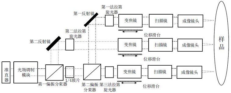
[0063] like image 3As shown, the sample arm includes a collimator, an optical field modulation module, a first and a second polarizing beam splitter, a first to a third Faraday rotator, a 1 / 4 glass slide, a first and a second mirror and a three-way Sample arm branch; the second port of the universal fiber coupler is connected to the collimator of the ...

Embodiment 2

[0068] In this embodiment, the sample is the eye, and among the three sample arm branches, the first and third sample arm branches are the optical path of the posterior segment of the eye, and the second sample arm branch is the optical path of the anterior segment of the eye; when imaging the posterior segment of the eye , there is a lens-like medium between the sample and the imaging lens, so the imaging lens of the posterior segment optical path adopts a 4F imaging lens. When imaging the anterior segment, there is no lens-like medium between the sample and the imaging lens, so the optical path of the anterior segment The imaging lens adopts focusing imaging lens; the optical path of the anterior segment coincides with the optical axis of the eye; the angle between the first optical path of the posterior segment and the optical axis of the eye is 10°~40°; the optical path of the second posterior segment and the optical axis of the eye The included angle is preferably -10°~-40...


PUM


Abstract

The invention discloses a multi-beam polarization OCT imaging device and an imaging method thereof. The invention uses a light field modulation module to change the Gaussian beam into a non-diffraction beam, thereby improving the resolution of the OCT image; beams to n sample arm branches, and further control the polarization state of each sample arm branch; the present invention can realize a large imaging field of view, and simultaneous imaging of multiple sample arm branches can greatly reduce field curvature and distortion caused by a large field of view, Improve the image quality, reduce the influence of aberration, and have higher resolution; through the proposed multi-optical path scheme, the whole eye polarized OCT imaging can be quickly realized; the invention solves the problem of the sample by introducing the first attenuation compensation amplifier and the second attenuation compensation amplifier The light intensity scattered back at different depths decays exponentially with the increase of depth, which leads to the problem of low signal-to-noise ratio of deep samples and improves the contrast of OCT images.

Description

technical field [0001] The invention relates to optical imaging technology, in particular to a multi-beam polarized OCT imaging device and an imaging method thereof. Background technique [0002] Optical coherence tomography (OCT) technology is based on the principle of low-coherence light interference. It can image human tissues in real time, non-destructively, and dynamically with high resolution. It can also be combined with optical coherence tomography angiography algorithms without injecting contrast agents. Subcutaneous microcirculation imaging can be realized. It has proven to be an important tool in the detection and study of diseases of the skin, blood vessels and even the eyes. Compared with common visible light, remote sensing, infrared imaging, etc., polarization imaging can obtain multi-dimensional polarization information of objects, which has very significant and unique advantages in the field of image vision. Polarization OCT can be used to obtain three-dim...

Claims


Application Information

Patent Timeline
Patent Type & Authority Patents(China)
IPC IPC(8): A61B3/10
Inventor 任秋实胡毅成黄智宇周传清
Owner PEKING UNIV
Why Eureka
Try Eureka