
Endoscope handle, endoscope and endoscope system

A technology for endoscopes and handles, applied in the fields of endoscopes, surgery, medical science, etc., can solve problems such as the narrow wiring space of the signal line 32, the shift of the center of gravity of the grip part of the handle, and interference with the doctor's operating hand or arm, etc., to achieve Reduce the difficulty of production, reduce the difficulty of wiring, and improve the effect of anti-interference

Pending Publication Date: 2022-04-12
MICROPORT UROCARE +1
View PDF0 Cites 0 Cited by
  • Summary
  • Abstract
  • Description
  • Claims
  • Application Information

AI Technical Summary

Problems solved by technology

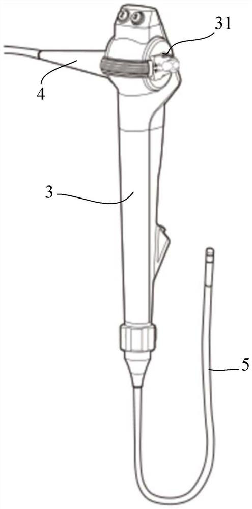
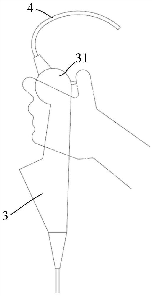
However, in view of the doctor's usual hand-holding posture and the posture of manipulating the handle of the endoscope to operate the handwheel, when the cable 4 is drawn out from the upper part of the handle body 3, and the cable 4 is usually a relatively bulky optical fiber (or light beam), causing the wire The cable 4 is easy to interfere with the doctor's operating hand or arm, and it is also easy to cause the center of gravity of the grip part of the handle to move upward, which not only causes unstable grip, but also increases the doctor's operating burden, which is not conducive to surgical operations
In addition, the operating handwheel 31 and the corresponding pull wires 33 are basically concentrated on the upper part of the handle. Therefore, the signal wire 32 in the handle body 3 needs to find a gap for routing from the operating handwheel 31, which not only results in a narrow wiring space for the signal wire 32 , wiring is difficult, and it increases the difficulty of structural design, and the signal line 32 is also easy to interfere with the pull line 33
In addition, for disposable endoscopes, the cable 4 is usually inseparably arranged on the handle body 3, resulting in the cable 4 being discarded together with the handle body 3, which significantly increases the cost
In addition, the image signals of traditional endoscopes are transmitted through analog signals, which has the problem of poor imaging quality due to long transmission distances

Method used


Image

  • Endoscope handle, endoscope and endoscope system
  • Endoscope handle, endoscope and endoscope system
  • Endoscope handle, endoscope and endoscope system

Examples


Embodiment Construction

[0056] Embodiments of the present invention are described below through specific examples, and those skilled in the art can easily understand other advantages and effects of the present invention from the content disclosed in this specification. The present invention can also be implemented or applied through other different specific implementation modes, and various modifications or changes can be made to the details in this specification based on different viewpoints and applications without departing from the spirit of the present invention. It should be noted that the diagrams provided in this embodiment are only schematically illustrating the basic idea of ​​the present invention, and only the components related to the present invention are shown in the diagrams rather than the number, shape and shape of the components in actual implementation. Dimensional drawing, the type, quantity and proportion of each component can be changed arbitrarily during actual implementation, ...


PUM


Abstract

The invention relates to an endoscope handle, an endoscope and an endoscope system, the endoscope system comprises an endoscope, an image processor and a display, the endoscope is in communication connection with the image processor through a cable, and the image processor is in communication connection with the display. The endoscope comprises a handle body, a wire outlet used for leading out an external cable is formed in the handle body, the handle body is provided with a holding area, and the wire outlet is formed in the side, facing the far end of the handle body, of the holding area. The endoscope handle has the advantages that the burden of a user holding the endoscope handle is relieved, the holding stability is improved, the wiring difficulty of an internal signal line is reduced, and the image signal transmission quality is improved.

Description

technical field [0001] The invention relates to the technical field of medical instruments, in particular to an endoscope handle, an endoscope and an endoscope system. Background technique [0002] An endoscope is a commonly used medical device that can be used in various inspections and surgical procedures. Compared with traditional surgery, functional minimally invasive surgery with medical endoscope has been widely accepted by doctors and patients. As long as the medical endoscope uses the natural hole of the human body or opens a small hole when necessary, the doctor can perform the airtight operation in the body outside the body as long as the endoscope lens is deep into the body proficiently. [0003] In traditional endoscopic surgery, the doctor manually controls the endoscope to reach the designated position through the handle body, and then performs the corresponding surgical operation. For example figure 1 The shown endoscope includes a handle body 3, the handle...

Claims


Application Information

Patent Timeline
Patent Type & Authority Applications(China)
IPC IPC(8): A61B1/00A61B1/04
CPCA61B1/00A61B1/04
Inventor 刘丹李中华刘畅刘民管鑫
Owner MICROPORT UROCARE
Learn More