Safety explosion-proof compensator
A compensator and safety-type technology, which is applied in expansion compensating devices for pipelines, pipe components, mechanical equipment, etc., can solve problems such as unsatisfactory resistance to thermal stress, influence on pipelines, and pipeline rupture, so as to reduce thermal stress , Enhance the effect of resistance, increase the effect of space
- Summary
- Abstract
- Description
- Claims
- Application Information
AI Technical Summary
Problems solved by technology
Method used
Image
Examples
Embodiment 1
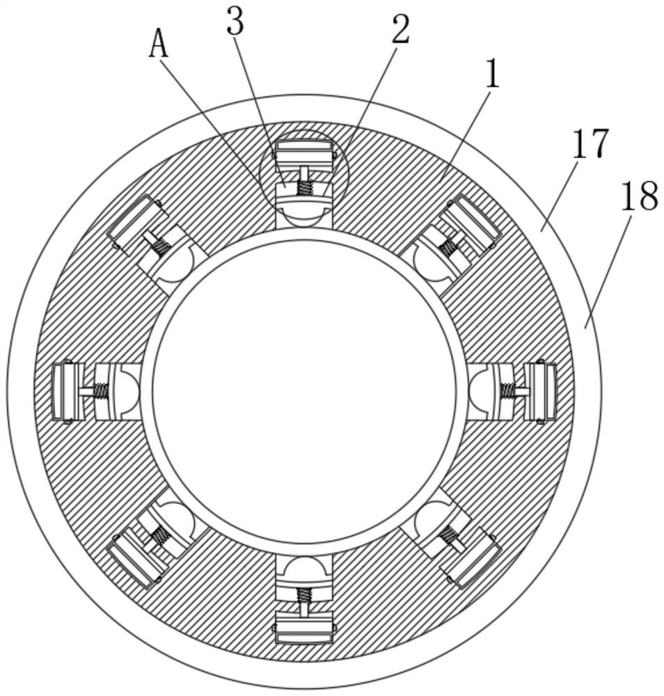
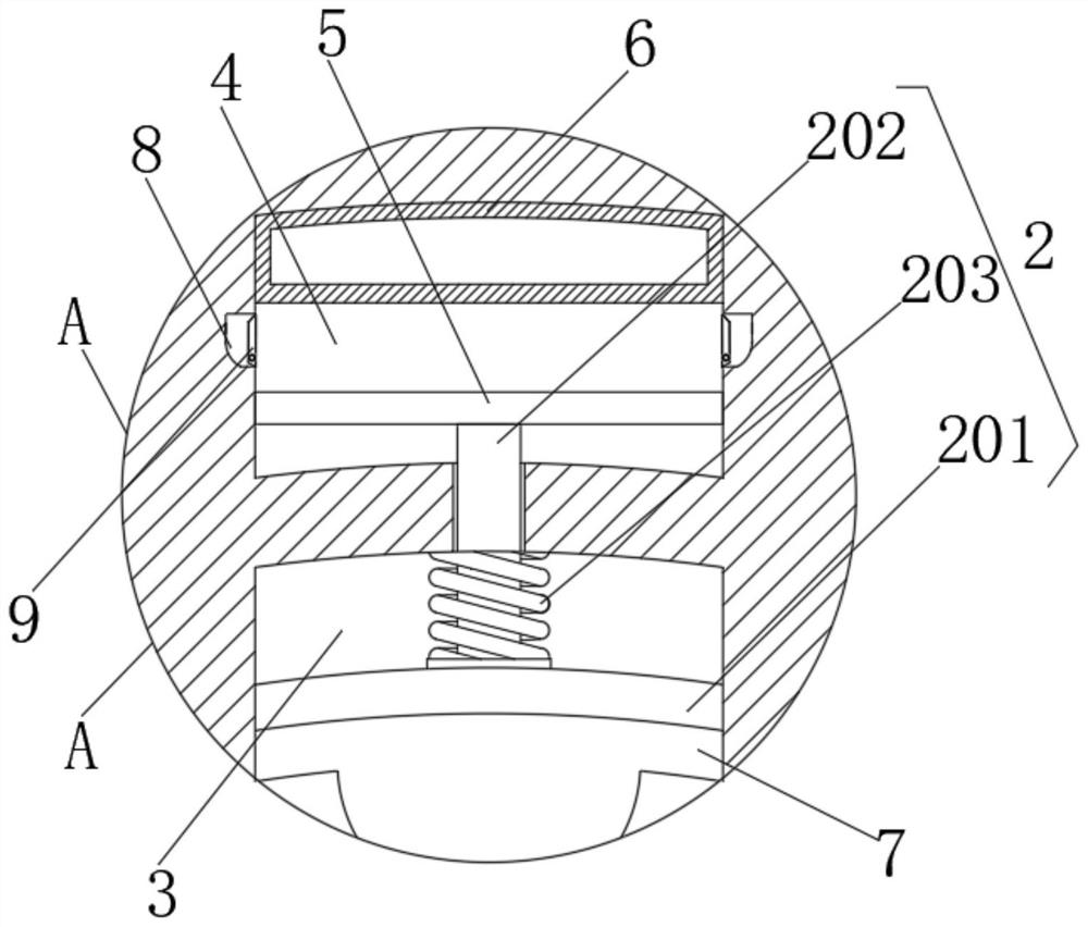
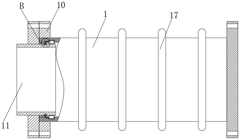
[0030] see figure 1 and figure 2 , a safety type explosion-proof compensator, including a pipe body 1 and a pipe 11, the pipe 11 is arranged inside the port of the pipe body 1, the surface of the pipe 11 and the pipe body 1 is provided with a flange 10, and the inner wall of the pipe body 1 is provided with a hole Cavity 3, the inner wall of the cavity 3 is provided with a compression component 2, the interior of the pipe body 1 is provided with an expansion tube 18, the expansion tube 18 and the compression component 2 are provided with a rubber cushion 7, and the compression component 2 includes a compression plate 201 , movable bar 202 and spring 203, one side of anti-pressure plate 201 is fixedly connected with the end face of movable bar 202, and one end of spring 203 is arranged on the side of anti-pressure plate 201, and the end face of anti-pressure plate 201 and the inner wall of cavity 3 Flexible connection, the end of the spring 203 away from the anti-pressure pla...
Embodiment 2
[0033] see figure 1 and figure 2 , the end face of the movable rod 202 is fixedly connected with a piston block 5, the inner wall of the pipe body 1 is provided with an empty chamber 4, the piston block 5 is movably connected with the inner wall of the empty chamber 4, and the inner wall of the empty chamber 4 is fixedly installed with a rubber air cushion 6. The pad 7 is fixedly mounted on the inner wall of the cavity 3, one side of the rubber cushion 7 is movably attached to the side of the pressure-resistant plate 201 and one side is in contact with the outer wall of the expansion tube 18,
[0034] The difference from Embodiment 1 is that a piston block 5 is added on the end face of the movable rod 202 to facilitate the use of the piston block 5 to squeeze the gas inside the empty chamber 4, and cooperate with the rubber air cushion 6 inside the upper empty chamber 4 to shrink under pressure to weaken the movement. The active force on the rod 202 weakens the influence of ...
Embodiment 3
[0036] see figure 1 , image 3 and Figure 4 The inside of the side wall of the pipe body 1 is provided with a sealing assembly 12, the surface of the pipe 11 is provided with a septum 14 suitable for the sealing assembly 12, the surface of the pipe 11 is provided with a sealing groove 13 for installing the septum 14, and the sealing assembly 12 Including airbag 121, conduit 122 and rubber inflatable pad 123, conduit 122 is fixedly installed between the airbag 121 and rubber inflatable pad 123, both airbag 121 and rubber inflatable pad 123 are fixedly installed in the inner wall of pipe body 1, and the surface of pipe 11 is set There is a first sealing ring 15, and the inner wall of the pipe body 1 is provided with a second sealing ring 16, and the first sealing ring 15 and the second sealing ring 16 are fitted together.
[0037] The difference from Embodiment 2 is that a sealing assembly 12 is provided in the side wall of the pipe body 1, so that the air bag 121 in the seal...
PUM
 Abstract
Description
Claims
Application Information
 - Generate Ideas
- Intellectual Property
- Life Sciences
- Materials
- Tech Scout
- Unparalleled Data Quality
- Higher Quality Content
- 60% Fewer Hallucinations
Browse by: Latest US Patents, China's latest patents, Technical Efficacy Thesaurus, Application Domain, Technology Topic, Popular Technical Reports.
© 2025 PatSnap. All rights reserved.Legal|Privacy policy|Modern Slavery Act Transparency Statement|Sitemap|About US| Contact US: help@patsnap.com


