Cleaning device for ground lenses of optical glasses

A technology for optical glasses and a cleaning device, which is applied in the direction of cleaning methods using liquids, cleaning methods and utensils, chemical instruments and methods, etc., and can solve problems such as cumbersome operation steps

Inactive Publication Date: 2022-04-08
上饶市亚星光电仪器有限公司
View PDF1 Cites 3 Cited by
  • Summary
  • Abstract
  • Description
  • Claims
  • Application Information

AI Technical Summary

Problems solved by technology

[0005] In order to overcome the disadvantage that the existing lens cleaning device can only clean one side of the lens at a time, when cleaning the other side of the lens, it is necessary to clean the support rod and the cleaning head first. Both sides of the lens are cleaned, and the lens cleaning device for optical glasses with high cleaning efficiency after grinding

Method used


Image

  • Cleaning device for ground lenses of optical glasses
  • Cleaning device for ground lenses of optical glasses
  • Cleaning device for ground lenses of optical glasses

Examples


Embodiment 1

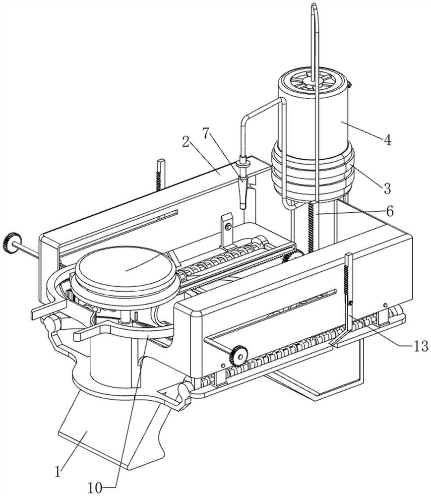
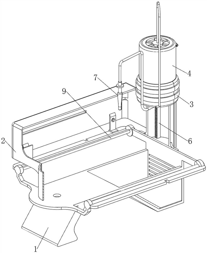
[0036] A lens cleaning device after grinding of optical glasses, referring to Figure 1-8 As shown, it includes a base 1, a side plate 2, a first mounting plate 3, a water tank 4, a lower pressing plate 5, a first rack 6, a nozzle 7, a first spring 8, a first guide rod 9, a clamping mechanism 10 and The moving mechanism 11, the top left side of the base 1 is provided with a side plate 2 by welding, the right side of the side plate 2 is provided with a first mounting plate 3, the bottom of the first mounting plate 3 is connected to the base 1, and the inside of the first mounting plate 3 passes The welding mode is provided with a water tank 4, and the water tank 4 is used to hold water for cleaning work. The middle part of the right side of the water tank 4 is slidingly provided with a lower pressure plate 5, and a first spring 8 is connected between the lower part of the rear side of the lower pressure plate 5 and the water tank 4. The front side of the bottom of the pressure ...

Embodiment 2

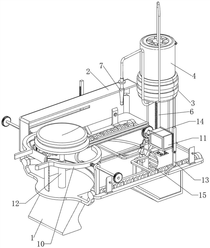
[0041] On the basis of embodiment 1, refer to figure 2 , Figure 9 and Figure 10 As shown, it also includes a placement mechanism 12, which is convenient for the clamping plate 101 to clamp the lens. The placement mechanism 12 includes a second hollow cylinder 120, a placement plate 121 and a fifth spring 122. The left side of the top of the base 1 is welded The second hollow tube 120 is provided in the same way, the second hollow tube 120 is slidingly provided with a placement plate 121, the placement plate 121 is used to place the lens, and the fifth spring 122 is connected between the bottom of the placement plate 121 and the second hollow tube 120 .

[0042] refer to figure 2 and Figure 11 As shown, a turning mechanism 13 is also included, and the turning mechanism 13 can automatically rotate the lens. The turning mechanism 13 includes a second gear 130, a second guide rod 131, a sixth spring 132, a connecting plate 133 and a third rack 134, The outer ends of the ...


PUM


Abstract

The invention relates to a cleaning device used after lens grinding, in particular to a cleaning device used after lens grinding of optical glasses. According to the cleaning device for the polished lenses of the optical glasses, the two faces of the lenses can be cleaned at the same time, and the cleaning efficiency is high. According to the technical scheme, the cleaning device for the ground lenses of the optical glasses comprises a base, a side plate, a first mounting plate, a water tank, a lower pressing plate and the like, the side plate is arranged on the left side of the top of the base, the first mounting plate is arranged on the right side of the side plate, and the bottom of the first mounting plate is connected with the base; a water tank used for containing water for cleaning work is arranged in the first mounting plate, and a lower pressing plate is slidably arranged in the middle of the right side of the water tank. After the lens is clamped by the clamping plate, the lens can be driven to rotate by rotating the clamping plate in the cleaning process, so that the front side and the back side of the lens can be cleaned, and the situation that when the lens is held by hand, the position where the lens is held by hand cannot be washed can be avoided.

Description

technical field [0001] The invention relates to a device for cleaning a lens after grinding, in particular to a device for cleaning a lens after grinding of optical glasses. Background technique [0002] After the optical lens is ground, the lens needs to be rinsed to prevent the residual powder on the lens from affecting the normal use of the lens. [0003] Patent application number CN202023225969.9 discloses an optical lens cleaning device, which includes a base, a support mechanism installed on the surface of the base, a bracket erected above the base, and a cleaning mechanism installed on the bracket. The support mechanism includes a plurality of vertically arranged Support rod, the top of the support rod is provided with a soft support head, and the position corresponding to the support rod on the bracket is provided with a vertical motor, and the bottom of the motor is connected with a rotating shaft and a soft cleaning head. The lenses are all cleaned, and the scope ...

Claims


Application Information

Patent Timeline
Patent Type & Authority Applications(China)
IPC IPC(8): B08B3/02B08B13/00
Inventor 陈继荣
Owner 上饶市亚星光电仪器有限公司
Why Eureka
Try Eureka