Cutter head lifting lug device

A lifting lug and cutter head technology, applied in the field of shield tunneling, can solve problems such as high risk, damage to the strength of the cutter head structure, and high difficulty

Pending Publication Date: 2022-04-05
CHINA RAILWAY CONSTR HEAVY IND
View PDF0 Cites 0 Cited by
  • Summary
  • Abstract
  • Description
  • Claims
  • Application Information

AI Technical Summary

Problems solved by technology

[0003] The hoisting of the shield cutter head was originally in the form of welded lifting lugs. In this way, the structure of the lifting lugs is simple and reliable, and it is highly operable during the manufacturing process in the workshop. Ears, grinding the position of the lifting lugs, and then repairing wear-resistant plates or surfacing welding at the corresponding positions. This operation process belongs to the category of high-altitude operations, which is difficult and risky
In addition, after the completion of the project, the cutter head dismantling, maintenance and reuse, etc. need to remove the wear-resistant plate at the lifting point or the wear-resistant surfacing welding, and then weld the lifting lug, which is time-consuming, laborious and material-consuming, and repeated welding and grinding , cutting and planing, etc. also damage the structural strength of the cutterhead itself, so this form of hoisting is gradually replaced, and detachable hoisting is beginning to be designed and used in practice

Method used


Image

  • Cutter head lifting lug device
  • Cutter head lifting lug device
  • Cutter head lifting lug device

Examples


Embodiment Construction

[0038] The following will clearly and completely describe the technical solutions in the embodiments of the present invention with reference to the accompanying drawings in the embodiments of the present invention. Obviously, the described embodiments are only some, not all, embodiments of the present invention. Based on the embodiments of the present invention, all other embodiments obtained by persons of ordinary skill in the art without making creative efforts belong to the protection scope of the present invention.

[0039] In order to enable those skilled in the art to better understand the solution of the present invention, the present invention will be further described in detail below in conjunction with the accompanying drawings and specific embodiments.

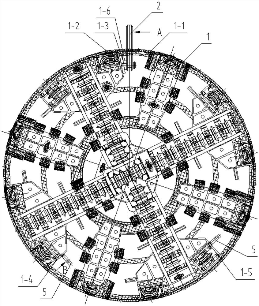
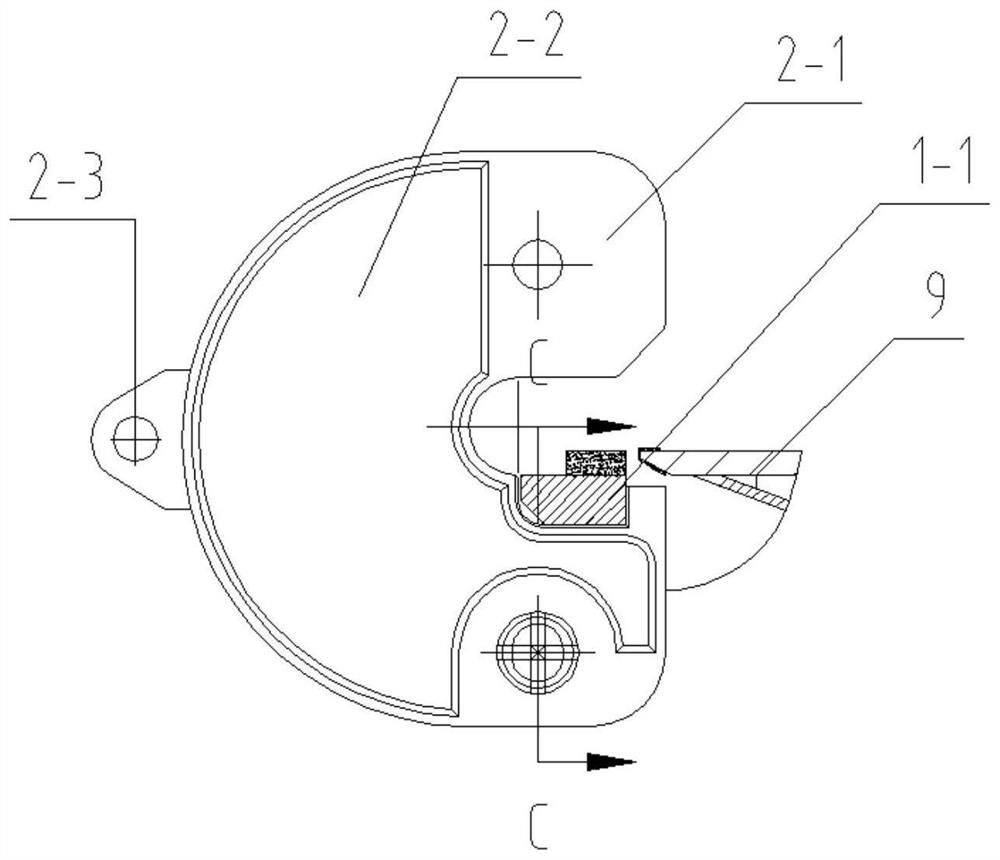
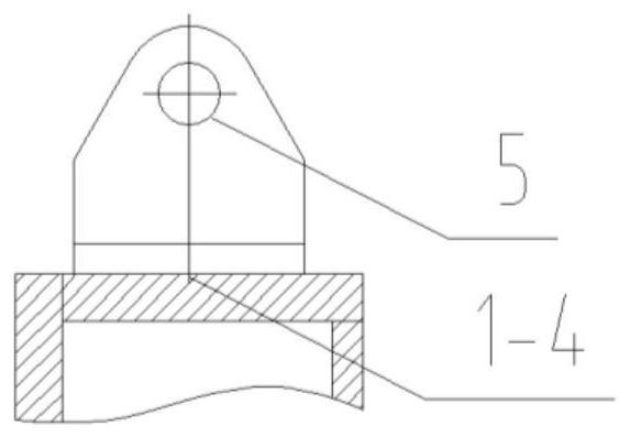
[0040] For the cutterhead lifting lug device provided in the embodiment of this application, refer to the attached figure 1 to attach Figure 6 , including: movable lifting lug 2, lifting lug fixing bolt 3 and fixe...


PUM


Abstract

The invention discloses a cutterhead lifting lug device which comprises a movable lifting lug, the movable lifting lug is provided with a hook groove, the hook groove is used for clamping and embedding a large circular ring of a cutterhead, the movable lifting lug is further provided with a kidney-shaped hole, and the kidney-shaped hole is located below the hook groove; one end of the lifting lug fixing bolt is used for penetrating through the waist-shaped hole and is fixed on the fixed sleeve of the cutter head; the fixed auxiliary turning lifting lug is used for fixing an edge cutter box plate adjacent to the cutter head; in the lifting process, the top of the movable lifting lug is fixed to the shackle, the hook groove is clamped and embedded in the large circular ring of the cutter head, the lifting lug fixing bolt is fixedly connected with the fixing sleeve through the kidney-shaped hole, and the cutter head is lifted by lifting the movable lifting lug and the fixed auxiliary turnover lifting lug.

Description

technical field [0001] The invention relates to the technical field of shield tunneling, in particular to a cutterhead lifting lug device. Background technique [0002] The cutter head is located at the front end of the shield machine and is an important component of the shield machine. In the processing and manufacturing of the shield cutter head, assembly and commissioning in the workshop, assembly on the construction site, disassembly after the completion of the project, repair and reuse of the cutter head, etc., it is necessary to hoist or turn over the cutter head. Throughout the whole process, the hoisting of the cutterhead needs to be carried out several times. How to lift the cutterhead safely, quickly, conveniently, reliably and economically is a question worth thinking about. [0003] The hoisting of the shield cutter head was originally in the form of welded lifting lugs. In this way, the structure of the lifting lugs is simple and reliable, and it is highly oper...

Claims


Application Information

Patent Timeline
IPC IPC(8): B66C1/66
Inventor 薛静邓汝群暨智勇任勇阳旭束龙康思杰
Owner CHINA RAILWAY CONSTR HEAVY IND
Why Eureka
Try Eureka