
Method for maintaining cooling assembly of metallurgical furnace

A technology for cooling components and metallurgical furnaces, which is applied in the direction of furnace components, furnace cooling devices, furnace cooling, etc., and can solve problems such as urgent maintenance or replacement time and short furnace shutdown time

Pending Publication Date: 2022-04-01
PAUL WURTH SA +1
View PDF12 Cites 0 Cited by
  • Summary
  • Abstract
  • Description
  • Claims
  • Application Information

AI Technical Summary

Problems solved by technology

Due to economic reasons, the downtime of the furnace should be as short as possible, so all repair or replacement work is time-critical

Method used


Image

  • Method for maintaining cooling assembly of metallurgical furnace
  • Method for maintaining cooling assembly of metallurgical furnace
  • Method for maintaining cooling assembly of metallurgical furnace

Examples


Embodiment Construction

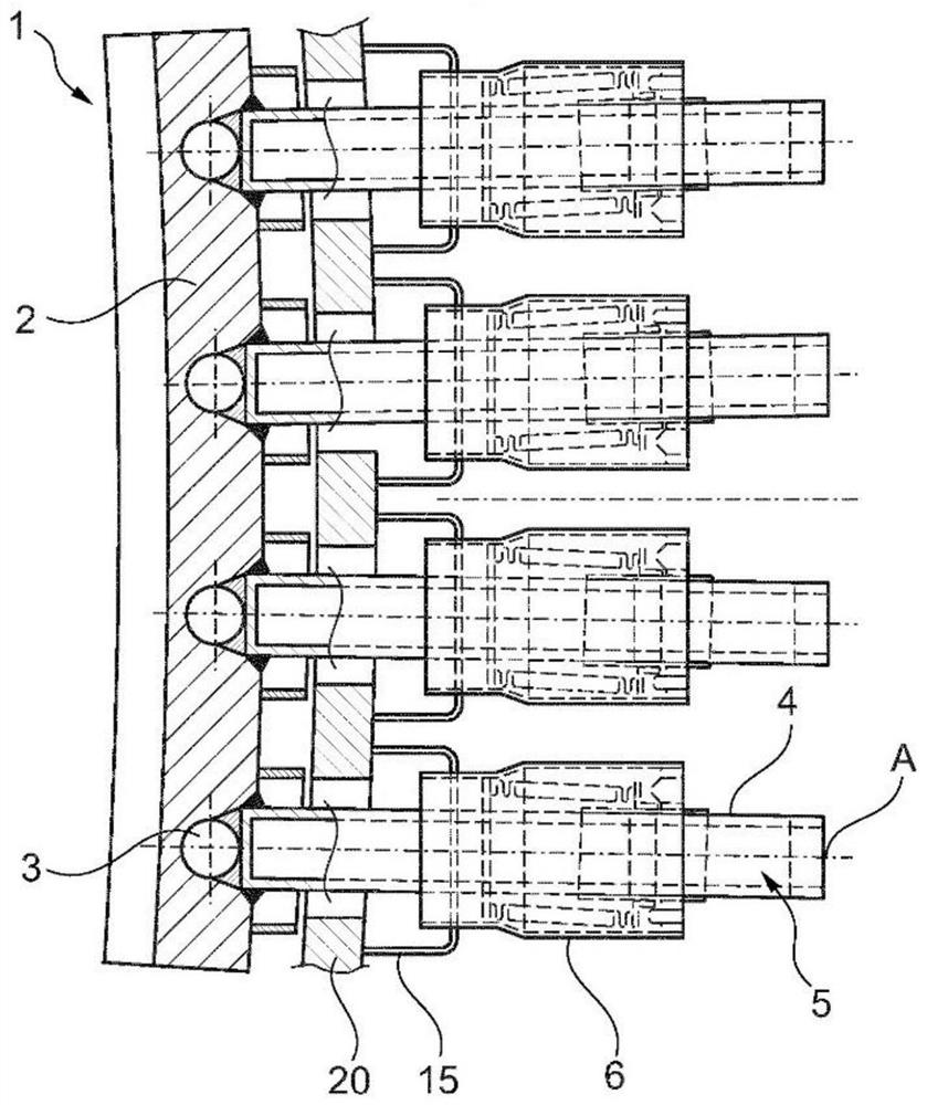
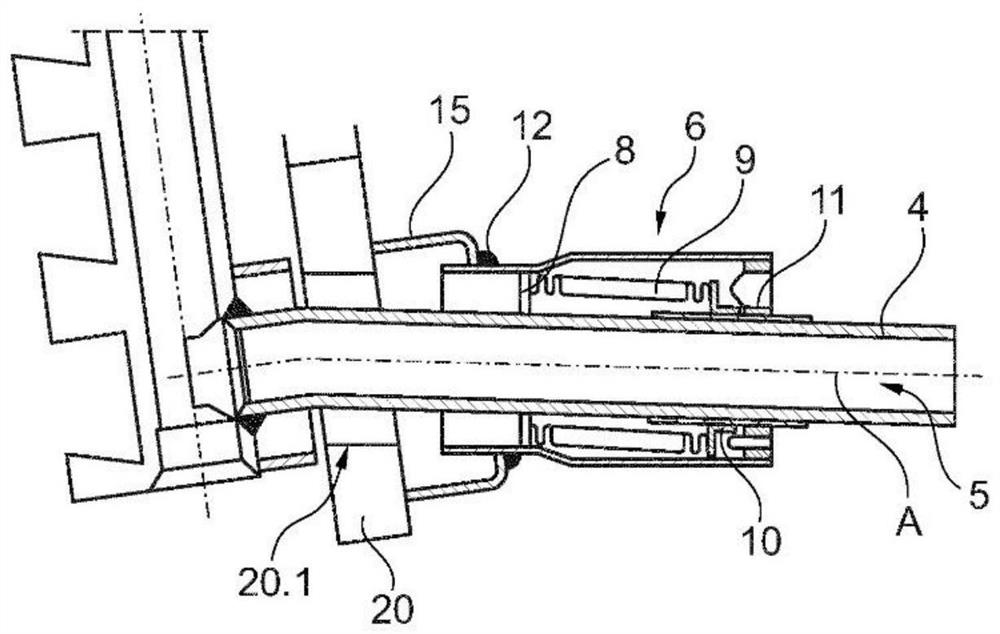
[0040] figure 1 A cross-sectional view of a cooling assembly 1 of a metallurgical furnace, such as a blast furnace, before maintenance is shown. cooling pack 1, in figure 2 Its details are also shown in the sectional view of , including the cooling plate 2 made of copper or copper alloy. The cooling plate 2 is arranged in the furnace shell 20 of the metallurgical furnace. The surface of the cooling plate 2 is shown here as flat, but it may include ribs and grooves to increase the surface area. Furthermore, it can also be provided with a refractory lining, which is not shown here for the sake of simplicity. A plurality of coolant channels 3 are provided in the cooling plate 2 .

[0041] The cooling assembly 1 also comprises a plurality of cooling tubes 4 each having a tube channel 5 connected to a cooling channel 3 . The cooling tube 4 can be made of the same material as the cooling plate 2 . Each cooling tube 4 passes through a housing opening 20 . 1 in the furnace hous...


PUM


Abstract

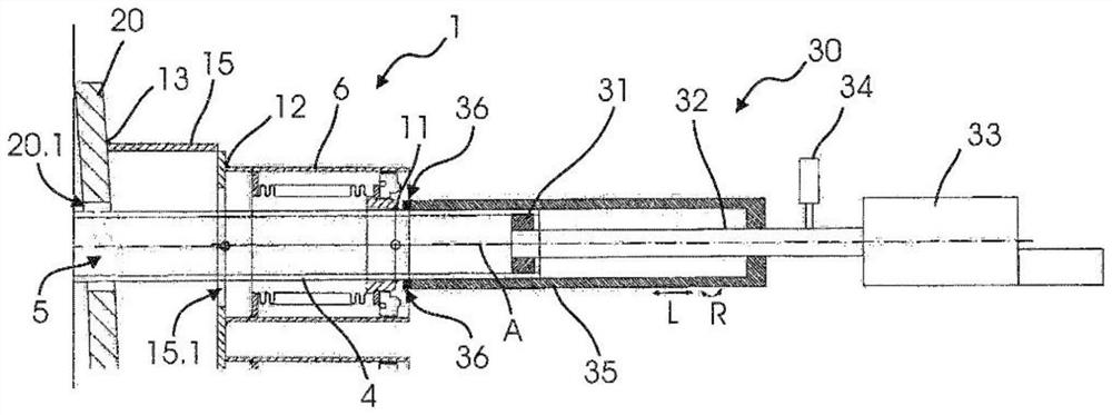
The invention relates to a method for maintaining a cooling assembly (1) of a metallurgical furnace, said cooling assembly (1) comprising: a cooling plate (2) arranged inside a furnace shell (20) of the metallurgical furnace; -a cooling tube (4) which traverses a casing opening (20.1) in the furnace casing (20) and is connected to the cooling plate (2); and-a compensator (6) arranged around the cooling tube (4) for forming a seal between the cooling tube (4) and the furnace shell (20). In order to provide measures to facilitate maintenance of a cooling system of a metallurgical furnace, the invention provides a method comprising performing at least one cutting operation with a cutting device (30, 40) comprising a clamp (31, 41) and a cutting tool (36, 45) movably connected to the clamp (31, 41) for a guided movement relative to the clamp (31, 41), the clamp (31, 41) is mounted to the cooling tube (4), whereby the cutting device (30, 40) is aligned with respect to the cooling tube (4) and the cutting tool (36, 45) is moved in a guided manner when the cutting operation is performed.

Description

technical field [0001] The invention relates to a method for maintaining cooling components of a metallurgical furnace. Background technique [0002] Cooling plates, also called staves, are used in metallurgical furnaces, for example in blast furnaces, as part of the furnace's cooling system. They are arranged inside the furnace shell. Its surface facing the inside of the furnace may be lined with a refractory material. The cooling plate has internal coolant channels which are connected to the rest of the cooling system, for example by cooling pipes which supply the coolant, usually water. The cooling tubes are guided through bore holes in the outer steel shell of the furnace. According to one configuration, the staves and the cooling tubes are made of copper (or copper alloy) and connected by welding. [0003] Due to wear and thermal stress during operation, the copper wall body may deform, eg bend or take a "banana" shape. Due to this deformation, the position and ang...

Claims


Application Information

Patent Timeline
IPC IPC(8): C21B7/10
CPCC21B7/10F27B1/24F27B3/24F27D1/12F27D9/00F27D2009/0024F27D2009/0029C21C5/4646F27D2001/0046
Inventor M.里克R.施奈德F.滕纳格尔斯N.马吉欧利
Owner PAUL WURTH SA
Learn More