LED surface mounting device with bulk material classification structure and implementation method thereof

A technology of LED patch and classification structure, applied in the direction of electrical components, electrical components, etc., can solve the problems of untimely blanking of LED patch lamps, influence of patch efficiency, and inability to check whether the size of LED chips is qualified or not.

Pending Publication Date: 2022-04-01
深圳市恒立泰科技有限公司
View PDF0 Cites 2 Cited by
  • Summary
  • Abstract
  • Description
  • Claims
  • Application Information

AI Technical Summary

Problems solved by technology

[0004] The object of the present invention is to provide an LED patch device with a bulk material classification structure and its implementation method, aiming at solving the above-mentioned background technology, the existing LED patch device cannot detect the LED chip when patching the rubber cake. Whether the specifications and sizes of the chips are qualified, so that the unqualified chips are sorted out, and the LED chip lamps processed by the existing LED chip placement device are not cut in time, occupying the station, resulting in unsatisfactory The problem that the efficiency of intermittent placement is affected

Method used


Image

  • LED surface mounting device with bulk material classification structure and implementation method thereof
  • LED surface mounting device with bulk material classification structure and implementation method thereof
  • LED surface mounting device with bulk material classification structure and implementation method thereof

Examples


Embodiment approach

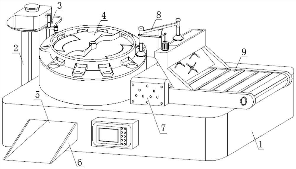
[0056] For a better demonstration, this embodiment provides an implementation method of an LED patch device with a bulk material classification structure, including the following steps:

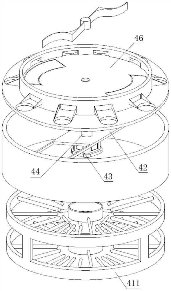
[0057] Step 1: Place a certain number of LED chips with patches in the distribution tray 46, start the drive motor 43 to cooperate with the rotating shaft 44 to drive the distribution tray 46 to rotate, and use the centrifugal force to push the chips to its edge when the distribution tray 46 rotates At the same time, the gear 442 on the outer wall of the protruding rod 441 on the top of the rotating shaft 44 meshes with the gear ring 472 inside the fixed sleeve 471, and cooperates with the centrifugal force to drive the shifting plates 473 on both sides of the fixed sleeve 471 to move the chips, and move them from the distribution tray. The sorting port 48 on the side wall of 46 is discharged and slides down to the patch groove 410 on the top of the rotating disk 45 by means of the inclined sl...


PUM


Abstract

The invention discloses an LED chip mounting device with a bulk material classification structure and an implementation method of the LED chip mounting device, belongs to the technical field of LED chip mounting, and aims to solve the problem that an existing LED chip mounting device cannot detect the size of an LED chip during rubber cake mounting so as to sort out unqualified chips. And the problem that the uninterrupted chip mounting efficiency is influenced due to the fact that the processed LED chip mounting lamp is not timely discharged and occupies a station when the existing LED chip mounting device is used for carrying out chip mounting on the rubber cake is solved. The driving motor and the rotating shaft drive the rotating disc and the material distribution tray to rotate, and the rotating shaft drives the material stirring device at the top of the material distribution tray to centrifugally rotate to stir LED chips to be subjected to surface mounting during rotation, so that qualified chips enter the surface mounting grooves in the rotating disc from the sorting openings in the side wall of the material distribution tray by means of the inclined slide ways, and the chips with over-specification are intercepted; meanwhile, the two ends of the chip mounting assembly are sequentially subjected to chip mounting adsorption feeding and finished adsorption discharging under the pushing of the lever; according to the invention, the LED chips to be subjected to chip mounting can be fully sorted, and the uninterrupted cyclic operation of chip mounting is realized.

Description

technical field [0001] The invention relates to the technical field of LED patching, in particular, an LED patching device with a bulk material classification structure and an implementation method thereof. Background technique [0002] LED patch lamp (SMD) is made of FPC circuit board, LED lamp, and high-quality silicone sleeve. Waterproof performance, safe and convenient to use low-voltage DC power supply, various luminous colors, bright colors; outdoor use can resist UV aging, yellowing, high temperature and other advantages, this product is widely used in building outline lights, entertainment quasi-decorative lighting, advertising decoration Lighting lighting field. The packaging process of the SMD LED is to first configure the phosphor powder and epoxy resin to make a mold, then make a rubber cake with the epoxy resin mixed with the phosphor powder, and paste the rubber cake on the chip. Then filled with epoxy resin, so as to make the LED packaged in SMD. The size o...

Claims


Application Information

Patent Timeline
Patent Type & Authority Applications(China)
IPC IPC(8): H05K13/02H05K13/04H05K13/08
Inventor 段瑶陈继红
Owner 深圳市恒立泰科技有限公司
Why Eureka
Try Eureka