SAW device comprising mixed weighted reflecting grating and mixed weighted reflecting grating
A reflective grid and device technology, applied in the direction of electrical components, impedance networks, etc., can solve the problems of degrading the frequency response characteristics of SAW devices, unfavorable device miniaturization, and limited clutter suppression functions, so as to improve clutter suppression performance and increase frequency Response characteristics, the effect of improving the Q value
- Summary
- Abstract
- Description
- Claims
- Application Information
AI Technical Summary
Problems solved by technology
Method used
Image
Examples
Embodiment 1
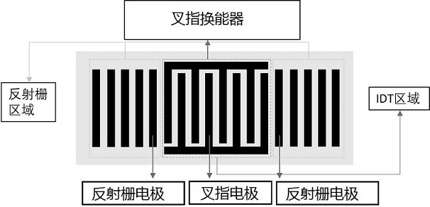
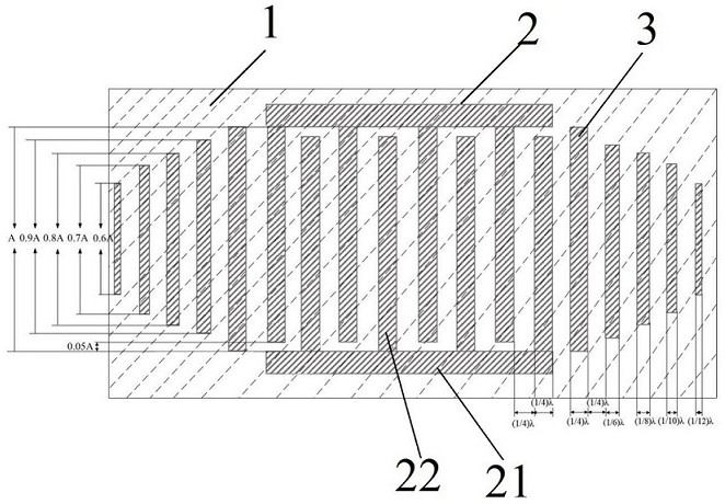
[0035] Such as figure 2 As shown, the present invention provides a SAW device comprising a hybrid weighted reflective grating, including a piezoelectric substrate 1, an interdigital transducer 2 and two hybrid weighted reflective gratings 3 disposed on the piezoelectric substrate 1 , two hybrid weighted reflective gratings 3 are arranged symmetrically with respect to the interdigital transducer.
[0036] In one example. Such as figure 2 As shown, the above-mentioned two hybrid weighted reflective gratings 3 are symmetrically arranged at both ends of the IDT 2 in the wave transmission direction, and are used to reflect the waves excited by the IDT 2 .
[0037] It should be noted that if the surface acoustic waves excited by the interdigital transducer 2 have multiple wave propagation directions, two hybrid weighted reflection gratings 3 can be symmetrically arranged at both ends of each wave propagation direction.
[0038] Such as figure 2 As shown, each hybrid weighted ...
Embodiment 2
[0058] Such as figure 2 As shown, the embodiment of the present invention provides a SAW device including a hybrid weighted reflective grid, the hybrid weighted reflective grid 3 includes a plurality of reflective grid electrodes distributed at equal intervals, and the length and width of the multiple reflective grid electrodes are equal to Decrease in the preset direction to form a hybrid weighting structure of width gradient weighting and apodization weighting.
[0059] Among them, the structure of the width gradient weighted reflective grating is as follows image 3 As shown, the electrode materials can be reduced and the device can be made more compact. The structure of the apodized weighted reflective grating is as follows Figure 4 As shown, the lateral clutter can be suppressed, the Q value of the SAW device can be increased, and the image 3 and Figure 4 Combining the two structures and integrating the advantages of the two structures can be obtained as figure 2...
Embodiment 3
[0068] This embodiment protects a hybrid weighted reflective grid, which includes multiple reflective grid electrodes distributed at equal intervals, and the lengths and widths of the multiple reflective grid electrodes decrease gradually in a preset direction.
[0069] An exemplary distribution function of the length of the reflective grid electrode in the hybrid weighted reflective grid is: ;in, l i Indicates the length of the i-th reflective grid electrode in the preset direction, A Indicates the length of the first reflective grid electrode in the preset direction, a Indicates the first preset parameter.
[0070] An exemplary distribution function of the width of the reflective grid electrode in the hybrid weighted reflective grid is: ;in, w i Indicates the width of the i-th reflective grid electrode in the preset direction, f represents the second preset parameter, b represents the third preset parameter, c Indicates the fourth preset parameter.
[0071] The d...
PUM
 Abstract
Description
Claims
Application Information
 - R&D
- Intellectual Property
- Life Sciences
- Materials
- Tech Scout
- Unparalleled Data Quality
- Higher Quality Content
- 60% Fewer Hallucinations
Browse by: Latest US Patents, China's latest patents, Technical Efficacy Thesaurus, Application Domain, Technology Topic, Popular Technical Reports.
© 2025 PatSnap. All rights reserved.Legal|Privacy policy|Modern Slavery Act Transparency Statement|Sitemap|About US| Contact US: help@patsnap.com


