
Sliding seat structure

A sliding seat and sliding seat cover technology are applied to indoor sanitary pipe installations, water supply installations, buildings, etc., which can solve the problems of laborious pressing and discomfort for consumers to adjust the height of the sliding seat, and achieve a simple appearance and low effort when pressing a pressure arm. , The effect of pressing the pressure arm is short

Active Publication Date: 2022-04-01
XIAMEN OCEANS SANITARY WARE CO LTD
View PDF6 Cites 0 Cited by
  • Summary
  • Abstract
  • Description
  • Claims
  • Application Information

AI Technical Summary

Problems solved by technology

The sliding structure of the existing slider is mostly a button pressing structure, which is very laborious to press, making consumers feel uncomfortable when adjusting the height of the slider

Method used


Image

  • Sliding seat structure
  • Sliding seat structure
  • Sliding seat structure

Examples


Embodiment Construction

[0044] In order to make the technical problems, technical solutions and beneficial effects to be solved by the present invention clearer and clearer, the present invention will be further described in detail below in conjunction with the accompanying drawings and embodiments. It should be understood that the specific embodiments described here are only used to explain the present invention, not to limit the present invention.

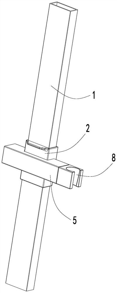
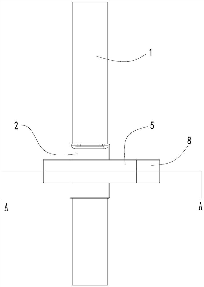
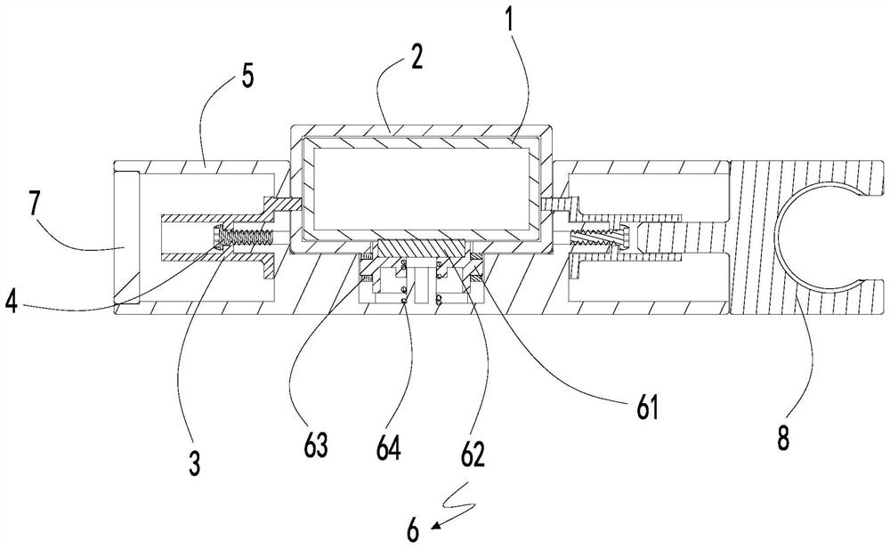
[0045] refer to Figure 1 to Figure 15 As shown, a preferred embodiment of the present invention is a sliding seat structure, including a sliding seat cover 2 that is movably sleeved on the rod 1, and a sliding seat body that is movably sleeved on the sliding seat cover 2 5. The hitch pin 3 for connecting the slider cover 2 and the slider main body 5, and the friction block assembly 6 inserted between the slider cover 2 and the slider main body 5, at the same time Press the sliding seat cover 2 and the sliding seat main body 5, and the friction block a...


PUM


Abstract

The invention discloses a sliding seat structure which comprises a sliding seat sleeve movably connected to a rod piece in a sleeving mode and a sliding seat body movably arranged on the sliding seat sleeve in a sleeving mode, and the sliding seat body is movably connected to the rod piece along with the sliding seat sleeve. The friction block assembly is connected between the sliding seat sleeve and the sliding seat body in an inserted mode, the sliding seat sleeve and the sliding seat body are pressed at the same time, the friction block assembly is detachably attached to the rod piece through the sliding seat sleeve or the sliding body, the sliding seat sleeve and the rod piece are movably and fixedly connected together, and operation can be achieved by pressing the sliding seat sleeve and the sliding seat body at the same time. Operation is simple and the structure is reasonable; rolling displacement is converted into pressing displacement, a pressing force arm is short, pressing is labor-saving, and operation is easy.

Description

technical field [0001] The invention relates to the technical field of bathroom products, in particular to a sliding seat structure. Background technique [0002] In modern bathrooms, there are usually shower equipment, such as shower rods, showers, etc., and usually the shower equipment will be equipped with a hand shower plugged into a socket. Generally, this socket will not be installed on the wall separately, but will be It is installed on the rod of the shower equipment, and the socket is installed on the rod. Usually, the socket is installed on the sliding seat to realize the installation, and the sliding seat can move on the rod, so that the user can use it according to his own height. to adjust the height of the sliding seat, thereby adjusting the spray height of the hand shower. Most of the sliding structures of the existing sliders are button-pressing structures, which are very laborious to press and make consumers feel uncomfortable when adjusting the height of t...

Claims


Application Information

Patent Timeline
Patent Type & Authority Applications(China)
IPC IPC(8): E03C1/06
Inventor 苏恭贺黄习林益龙范启华
Owner XIAMEN OCEANS SANITARY WARE CO LTD
Learn More