
Camera module

A camera module and module technology, which is applied in image communication, printing equipment, instruments, etc., can solve the problems of increasing the number of soldering and solder paste consumption, increasing the risk of camera damage, and adversely affecting the yield of camera modules. Effects of shake and/or reduced autofocus performance, ease of assembly, and improved reliability

Pending Publication Date: 2022-03-29
NINGBO SUNNY OPOTECH CO LTD
View PDF0 Cites 0 Cited by
  • Summary
  • Abstract
  • Description
  • Claims
  • Application Information

AI Technical Summary

Problems solved by technology

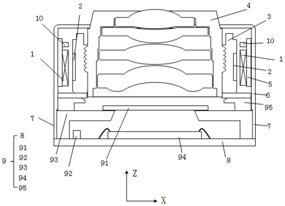
At this time, in order to realize the electrical connection of each electrical element, the driver usually needs to have at least two pins 7, and each pin 7 has at least six sub-pins (usually the position sensing element needs to draw 2-4 sub-pins). pins), too many sub-pins lead to an increase in driver size
And the pin 7 is usually soldered on the module circuit board 8 (that is, the circuit board of the photosensitive component 9), too many sub-pins will increase the number of soldering times and the amount of solder paste, which will lead to an increased risk of damage to the camera during soldering , which is not conducive to improving the yield rate of camera module production

Method used


Image

  • Camera module
  • Camera module
  • Camera module

Examples


Embodiment Construction

[0046] For a better understanding of the application, various aspects of the application will be described in more detail with reference to the accompanying drawings. It should be understood that these detailed descriptions are descriptions of exemplary embodiments of the application only, and are not intended to limit the scope of the application in any way. Throughout the specification, the same reference numerals refer to the same elements. The expression "and / or" includes any and all combinations of one or more of the associated listed items.

[0047] It should be noted that in this specification, expressions of first, second, etc. are only used to distinguish one feature from another, and do not represent any limitation on the features. Accordingly, a first body discussed hereinafter may also be referred to as a second body without departing from the teachings of the present application.

[0048] In the drawings, the thickness, size and shape of objects have been slight...


PUM


Abstract

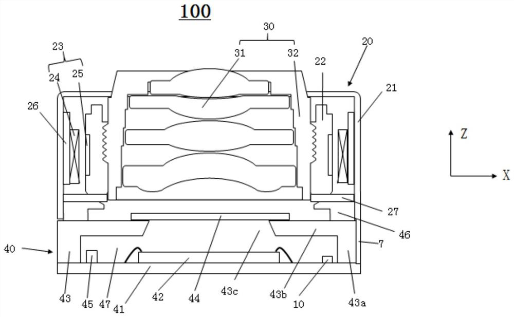
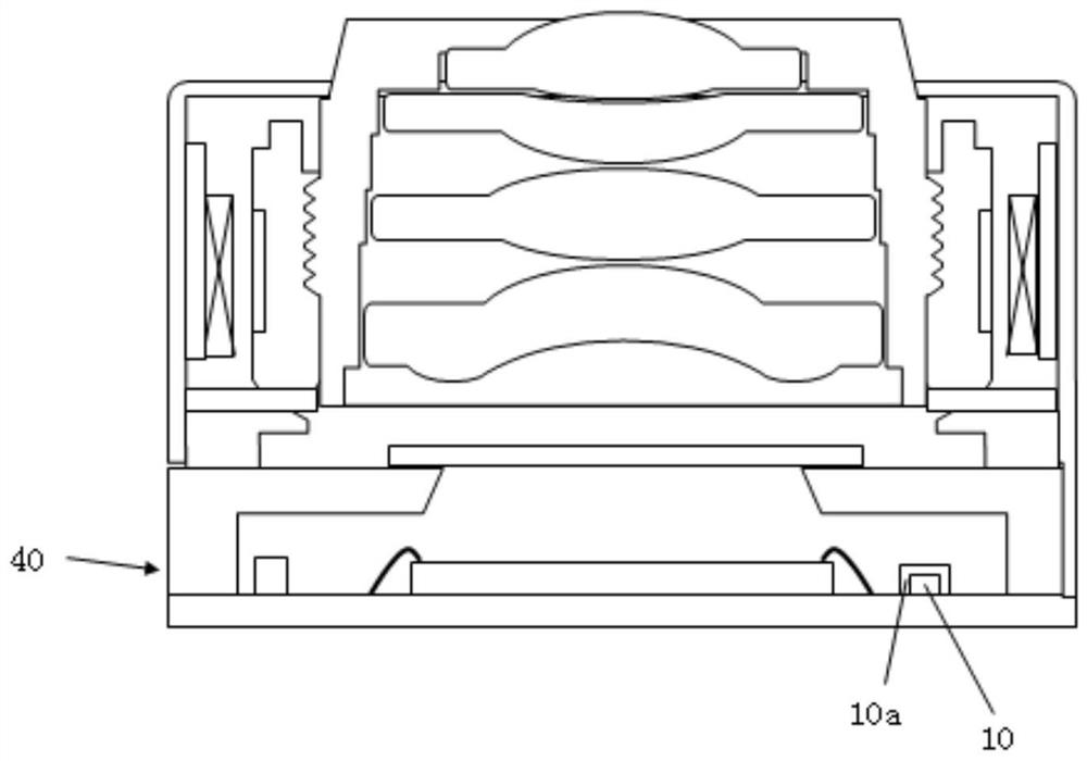
The invention relates to a camera module comprising a driver which comprises a shell, a carrier and at least one driving module; an optical lens; the photosensitive component comprises a module circuit board, a photosensitive chip and a bracket; wherein the photosensitive assembly further comprises at least one position sensing element installed on the upper surface of the module circuit board, and the position sensing element is used for sensing the change of a magnetic field formed by the magnet of the driving module so as to obtain the position change of the carrier relative to the photosensitive chip; and the position sensing element is positioned in an area between the outer side surface of the bracket and the photosensitive chip. According to the invention, the size of the camera module with the position sensor can be reduced, and the anti-shake and / or automatic focusing performance of the camera module can be improved or ensured.

Description

technical field [0001] The invention relates to the technical field of camera equipment, in particular, the invention relates to a compact camera module with a motor. Background technique [0002] With the increasing demand of consumers for mobile phone photography, the functions of mobile phone cameras (that is, camera modules) are becoming more and more abundant. Functions such as portrait shooting, telephoto shooting, optical zoom, and optical image stabilization are all integrated into the camera with limited size. , and the function of optical anti-shake is more valued by consumers. In terms of photo shooting and video shooting, optical anti-shake has played a very important role. figure 1 A schematic cross-sectional view of a camera module with an optical image stabilization function is shown. refer to figure 1 , the camera module has the functions of auto focus and optical image stabilization, and its driver has at least two drive modules, which can respectively dri...

Claims


Application Information

Patent Timeline
Patent Type & Authority Applications(China)
IPC IPC(8): H04N5/225G02B7/09G03B5/00G03B13/36
CPCG02B7/09G03B13/36G03B5/00H04N23/50
Inventor 戎琦陈飞帆阙嘉耀俞丝丝王海涛郑雪莹蒋伟杰
Owner NINGBO SUNNY OPOTECH CO LTD
Learn More