
Driver fatigue detection system

A driver fatigue and fatigue detection technology, which is applied in the field of driver fatigue detection system, can solve the problems of inability to accurately detect whether the driver is tired, single judgment, loss of effect, etc., and achieve the effect of preventing continued drowsiness and eliminating limitations

Pending Publication Date: 2022-03-29
深圳市鑫鸿源业科技有限公司
View PDF6 Cites 2 Cited by
  • Summary
  • Abstract
  • Description
  • Claims
  • Application Information

AI Technical Summary

Problems solved by technology

[0003] In the prior art, there is a way to judge the fatigue degree by detecting whether the driver's head posture is often tilted downward, but this method is too simple to judge, and some people keep the head posture basically unchanged when they are tired, so this The method cannot accurately detect whether the driver is fatigued, which affects the accuracy of judgment
In addition, although the driver will not move his head so frequently when he is tired, when driving on some relatively empty roads, the driver will look ahead more when he judges that the car is in a safe state and will not be affected by the surroundings. The condition of the road surface, so infrequent head movement does not directly indicate that the driver is in a state of fatigue. It is easy to misjudge whether the driver is tired by detecting head movement.
[0004] Using the camera to capture the driver's face changes can also detect the driver's fatigue, but this method still has certain limitations
When the driver's face is covered, this detection method will lose its effect and cannot achieve the purpose of detection

Method used


Image

  • Driver fatigue detection system

Examples


Embodiment Construction

[0017] The following will clearly and completely describe the technical solutions in the embodiments of the present invention with reference to the accompanying drawings in the embodiments of the present invention. Obviously, the described embodiments are only some, not all, embodiments of the present invention. Based on the embodiments of the present invention, all other embodiments obtained by persons of ordinary skill in the art without making creative efforts belong to the protection scope of the present invention.

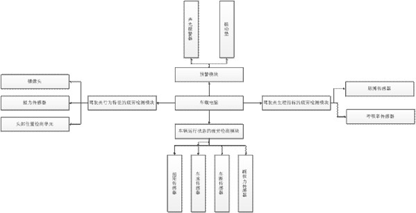
[0018] Reference attached figure 1 , a driver fatigue detection system, comprising a fatigue detection module of driver behavior characteristics, a fatigue detection module of driver physiological indicators, a fatigue detection module of vehicle running status, an early warning module and a vehicle-mounted computer, the fatigue detection module of the driver behavior characteristics The detection module, the fatigue detection module of the driver's physiologi...


PUM


Abstract

The invention relates to the field of data monitoring, in particular to a driver fatigue detection system. Comprising a driver behavior characteristic fatigue detection module, a driver physiological index fatigue detection module, a vehicle running state fatigue detection module, an early warning module and a vehicle-mounted computer, and the driver physiological index fatigue detection module is used for detecting the pulse frequency and the breathing frequency of a driver and sending the pulse frequency and the breathing frequency to the vehicle-mounted computer; the vehicle running state fatigue detection module is used for detecting the torque of a steering wheel, the running speed, the front vehicle distance and the brake pedal force, and the early warning module is used for receiving an early warning signal sent by a vehicle-mounted computer and then conducting early warning. According to the invention, the limitation of the detection method can be eliminated, and the fatigue condition of the driver can be accurately detected; when the vehicle-mounted computer judges that the driver is in the fatigue state, the vehicle-mounted computer starts an early warning module to give an early warning to the driver, and the driver is prevented from continuing to be sleepy.

Description

technical field [0001] The invention relates to the field of data monitoring, in particular to a driver fatigue detection system. Background technique [0002] With the rapid development of my country's transportation industry, fatigue driving is one of the main causes of traffic accidents. Fatigue detection has gradually attracted people's attention. Fatigue detection technologies have emerged in an endless stream, which has practical significance for preventing fatigue driving and reducing traffic accidents. [0003] In the prior art, there is a way to judge the fatigue degree by detecting whether the driver's head posture is often tilted downward, but this method is too simple to judge, and some people keep the head posture basically unchanged when they are tired, so this The method cannot accurately detect whether the driver is fatigued, which affects the accuracy of judgment. In addition, although the driver will not move his head so frequently when he is tired, when d...

Claims


Application Information

Patent Timeline
Patent Type & Authority Applications(China)
IPC IPC(8): G08B21/06G08B31/00
CPCG08B21/06G08B31/00
Inventor 徐永琴
Owner 深圳市鑫鸿源业科技有限公司
Learn More