Satellite-borne diffuse transmission type limb calibration mechanism

A diffuse transmission and calibration technology, applied in the field of satellite-borne diffuse transmission limb calibration mechanism, can solve the problems of performance degradation of the calibration plate, large rotational inertia, large installation size, etc., to reduce the rotation area and ensure the use of longevity, the effect of reducing performance degradation

Active Publication Date: 2022-03-29
HEFEI INSTITUTES OF PHYSICAL SCIENCE - CHINESE ACAD OF SCI
View PDF7 Cites 0 Cited by
  • Summary
  • Abstract
  • Description
  • Claims
  • Application Information

AI Technical Summary

Problems solved by technology

[0002] In the prior art, the limb calibration mechanism is implemented in the form that the rotation axis is perpendicular to the diffuse transmission calibration plate, and the calibration plate is installed on a turntable structure, which has a large rotation area, a large rotational inertia, and a large installation size. Larger disadvantages; there is also a part of the calibration mechanism. When the calibration plate is not in the calibration position, the calibration plate is not well protected, so that the sunlight will directly shine on the calibration plate, making the performance of the calibration plate attenuated and affecting Calibration effect

Method used


Image

  • Satellite-borne diffuse transmission type limb calibration mechanism
  • Satellite-borne diffuse transmission type limb calibration mechanism
  • Satellite-borne diffuse transmission type limb calibration mechanism

Examples


Embodiment Construction

[0023] In order to make the object, technical solution and advantages of the present invention clearer, the present invention will be further described in detail below in conjunction with the accompanying drawings and embodiments. It should be understood that the specific embodiments described here are only used to explain the present invention, not to limit the present invention. In addition, the technical features involved in the various embodiments of the present invention described below can be combined with each other as long as they do not constitute a conflict with each other.

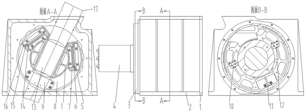
[0024] like figure 1 As shown, the spaceborne diffuse transmission type limb calibration mechanism of the present invention includes: a light-shielding cover plate 1 , a limb calibration box 2 , a motor base 3 and a stepping motor 4 . The stepping motor 4 is connected with the motor base 3 by screws, and the motor base 3 is connected with the calibration box 2 by screws. The edge calibration b...


PUM


Abstract

The invention provides a satellite-borne diffuse transmission type limb calibration mechanism. The device comprises a shading cover plate, a limb calibration box body, a motor seat, a stepping motor, a main calibration plate pressing plate, a main calibration plate, a main calibration plate seat, a stepping motor and calibration plate seat adapter plate, a backup calibration plate pressing plate, a backup calibration plate, a backup calibration plate seat, a counterweight copper block, a main microswitch, a microswitch gear lever and a backup microswitch. According to the invention, the rotary supporting structure that the rotating shaft is parallel to the diffuse transmission calibration plate surface is adopted, so that the defects of large rotation area, large inertia and large installation size are reduced; and a calibration plate protection groove structure is designed, so that the calibration plate can stay in the protection groove when sunlight calibration is not carried out, the calibration plate can be prevented from being directly irradiated by sunlight, small performance change of the calibration plate is ensured, and a relatively good calibration effect is realized. Meanwhile, a microswitch gear lever is provided to limit and position the rotating part by touching the microswitch, and a counterweight copper block is provided to enable the mass center of the rotating part to be located on the rotating shaft, so that the impact on the microswitch during instrument transportation and rocket launching is reduced.

Description

technical field [0001] The invention relates to a rotating movable part of a spaceborne instrument in the field of satellite optical instrument design, in particular to a spaceborne diffuse transmission type limb calibration mechanism. Background technique [0002] In the prior art, the limb calibration mechanism is implemented in the form that the rotation axis is perpendicular to the diffuse transmission calibration plate, and the calibration plate is installed on a turntable structure, which has a large rotation area, a large rotational inertia, and a large installation size. Larger disadvantages; there is also a part of the calibration mechanism. When the calibration plate is not in the calibration position, the calibration plate is not well protected, so that the sunlight will directly shine on the calibration plate, making the performance of the calibration plate attenuated and affecting Calibration effect. Contents of the invention [0003] In order to solve the ab...

Claims


Application Information

Patent Timeline
Patent Type & Authority Applications(China)
IPC IPC(8): G01J3/02G01J3/28
CPCG01J3/0202G01J3/0259G01J3/0297G01J3/28
Inventor 刘凤垒司福祺陈军曾议周海金
Owner HEFEI INSTITUTES OF PHYSICAL SCIENCE - CHINESE ACAD OF SCI
Why Eureka
Try Eureka