
Ultrasonic field separation device and system

A separation device and ultrasonic field technology, applied in grain processing and other directions, can solve the problems of complex structure, inability to effectively reduce the temperature of the grinding drum, and affecting the material separation efficiency.

Pending Publication Date: 2022-03-29
SHENZHEN KELI FORCE NANO ENG EQUIP CO LTD
View PDF0 Cites 0 Cited by
  • Summary
  • Abstract
  • Description
  • Claims
  • Application Information

AI Technical Summary

Problems solved by technology

However, this method can only cool down the temperature of the local surface, and a large amount of heat is concentrated inside when grinding, so that the temperature inside the grinding cylinder cannot be effectively reduced.
[0003]At the same time, the grinding system usually adopts a continuous grinding process, and it is necessary to discharge the grinding materials that meet the requirements without stopping the grinding, so as to be used in the subsequent process. Grinding balls (grinding media) and the material mixture will separate the materials that meet the requirements. The existing separators mostly use a separation screen structure. The separation port is blocked, which affects the separation efficiency of materials
At present, there are mainly two ways to separate the grinding balls and the finished materials in the ball milling system. One is static separation, that is, the separation screen is fixed between the material outlet and the grinding chamber. The separation screen of this structure is fixed when it is working. During the separation process, it is very easy to accumulate on the surface of the separation screen, block the separation port, and affect the separation efficiency; the second is dynamic separation, that is, the separation screen rotates at a high speed, and the centrifugal force generated by the rotation of the separation screen does not affect the separation efficiency. There are grinding balls or larger particles clogged or attached to the separator, while smaller grinding materials are discharged through negative pressure, which does not affect the separation efficiency, but its structure is complex, and the separator needs to be driven to rotate, which increases the power consumption of the equipment

Method used

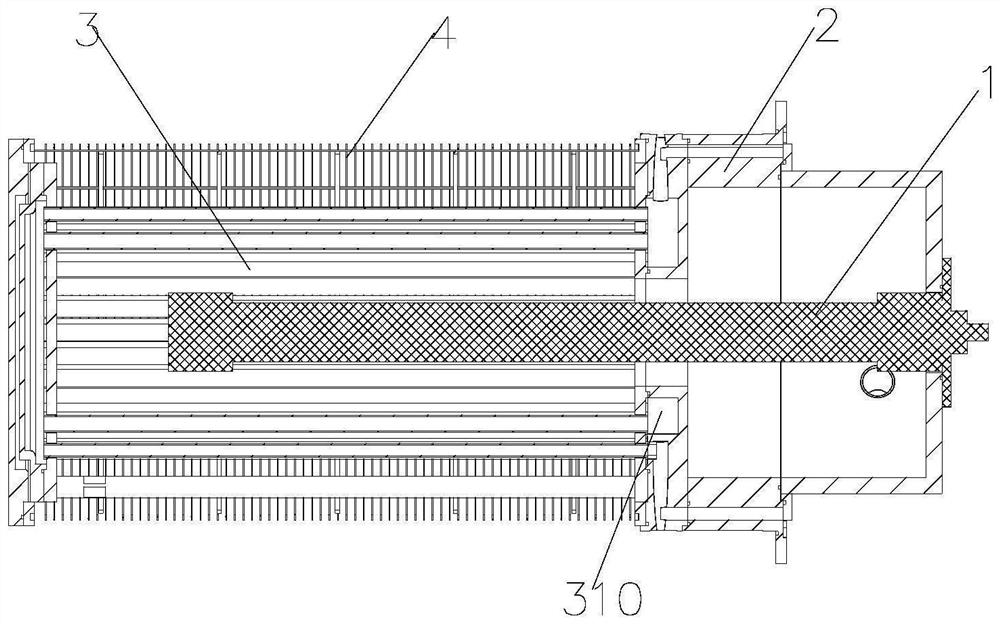
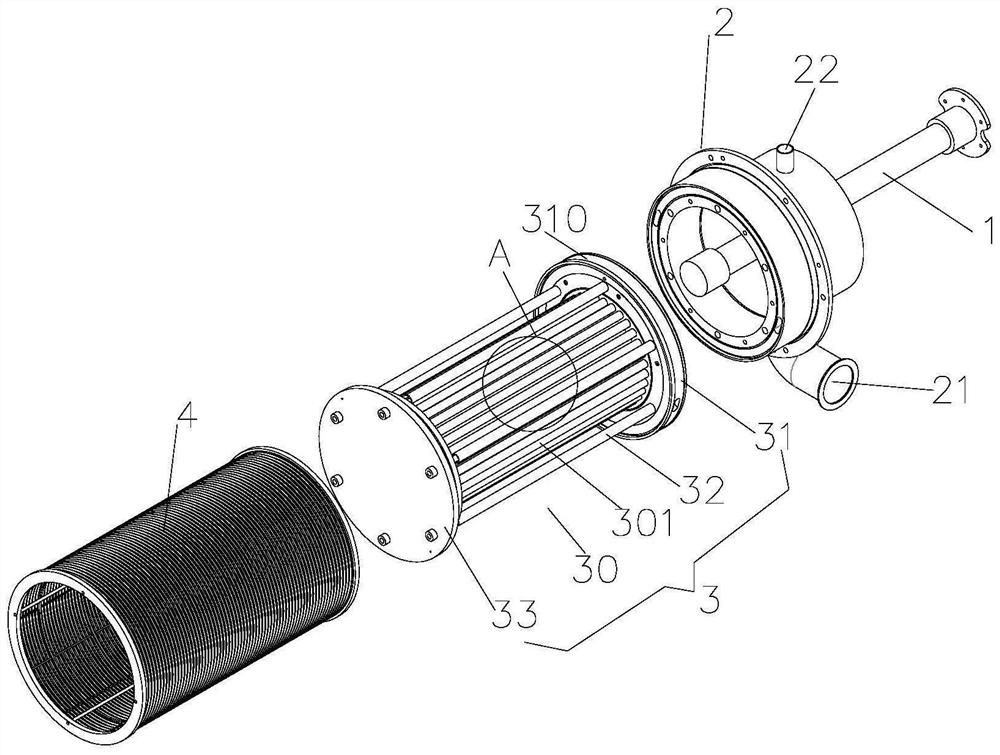
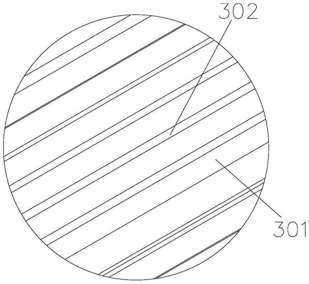

Image

  • Ultrasonic field separation device and system
  • Ultrasonic field separation device and system
  • Ultrasonic field separation device and system

Examples


Embodiment Construction

[0040] The claims of the present invention will be further described in detail below in conjunction with specific embodiments and accompanying drawings. Apparently, the described embodiments are only some of the embodiments of the present invention, not all of them. Based on the embodiments of the present invention, all other embodiments obtained by persons of ordinary skill in the art without creative work also fall within the protection scope of the present invention.

[0041] It should be understood that, in the descriptions of the embodiments of the present invention, all directional terms, such as "up", "down", "left", "right", "front", "rear", etc. indicate the orientation or position The relationship is based on the orientation and positional relationship shown in the drawings or the conventional orientation or positional relationship of the product of the invention in use, which is only for the convenience of simplifying the description of the present invention, rather ...


PUM


Abstract

The invention is suitable for the technical field of ball milling. The invention discloses an ultrasonic field separation device and system, the ultrasonic field separation device comprises a separator and an ultrasonic generator, and the separator is provided with a cooling mechanism. During use, an ultrasonic field is generated in the separator through the ultrasonic generator, and when the power of the ultrasonic generator is set to be large, the ultrasonic field can separate grinding materials on or around the separator from media, so that the separator is prevented from being blocked; and composite kinetic energy can be provided for grinding media, and the grinding efficiency is improved. Meanwhile, the grinding materials with small diameters are easily gathered, the grinding materials and the like outside the separator can be dispersed through the ultrasonic field, the grinding materials entering the separator can also be dispersed, and follow-up secondary dispersion treatment is avoided. And meanwhile, the working temperature of the ultrasonic generator is effectively reduced through the cooling mechanism, the reliability of continuous working is improved, and the gathering effect of heat on grinding materials with small diameters can be avoided.

Description

technical field [0001] The invention relates to the technical field of ball milling, in particular to an ultrasonic field separation device and system. Background technique [0002] The existing grinding system adopts the grinding ball method, through the interaction between the medium and the grinding material, the grinding and crushing are realized, and a large amount of heat is generated during the long-term continuous grinding process, and the grinding medium rises with the working temperature in the grinding chamber , the grinding efficiency is affected, and it also has an adverse effect on the equipment components. Usually, a cooling system needs to be installed during grinding, and the existing cooling system is usually installed on the grinding cylinder, so that part of the heat can be taken away to reduce the working temperature. However, this can only cool down the temperature of the local surface, and a large amount of heat is concentrated inside when grinding, s...

Claims


Application Information

Patent Timeline
Patent Type & Authority Applications(China)
IPC IPC(8): B02C17/10B02C17/18
CPCB02C17/1815B02C17/10B02C17/18
Inventor 陈波
Owner SHENZHEN KELI FORCE NANO ENG EQUIP CO LTD
Learn More