Frequency jitter device and switching power supply

A frequency jittering and switching circuit technology, applied in the field of switching power supplies, can solve the problems of complex frequency jittering circuit design, inability to effectively eliminate capacitor/inductor peak current and its harmonics, inability to effectively reduce EMI interference, etc. Current and its harmonics, the effect of reducing EMI interference

Pending Publication Date: 2022-03-25
NUBIA TECHNOLOGY CO LTD
View PDF0 Cites 0 Cited by
  • Summary
  • Abstract
  • Description
  • Claims
  • Application Information

AI Technical Summary

Problems solved by technology

[0007] In view of this, a frequency dithering device and a switching power supply provided by the embodiment of the present invention can solve the problem that the current frequency dithering circuit design is too complicated, and the peak current and its harmonics generated by the capacitor / inductance cannot be effectively eliminated, and the EMI cannot be effectively reduced. interference problem

Method used


Image

  • Frequency jitter device and switching power supply
  • Frequency jitter device and switching power supply
  • Frequency jitter device and switching power supply

Examples


Embodiment Construction

[0050]In order to make the technical problems, technical solutions and beneficial effects to be solved by the present invention clearer and more comprehensible, the present invention will be further described in detail below with reference to the accompanying drawings and embodiments. It should be understood that the specific embodiments described herein are only for explaining the present invention, but not for limiting the present invention.

[0051] In the following description, suffixes such as 'module', 'component' or 'unit' used to represent elements are used only to facilitate the description of the present invention and have no specific meaning per se. Thus, "module", "component" or "unit" may be used interchangeably.

[0052] It should be noted that the terms "first", "second" and the like in the description and claims of the present invention and the above drawings are used to distinguish similar objects, and are not necessarily used to describe a specific sequence o...


PUM


Abstract

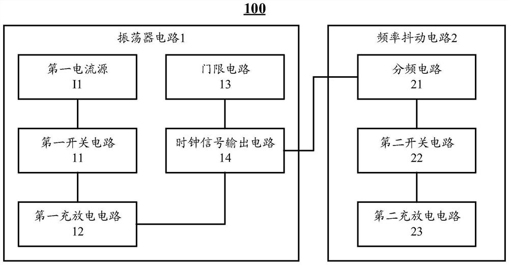
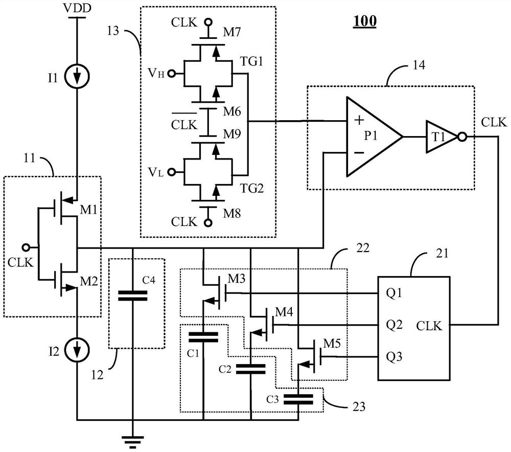
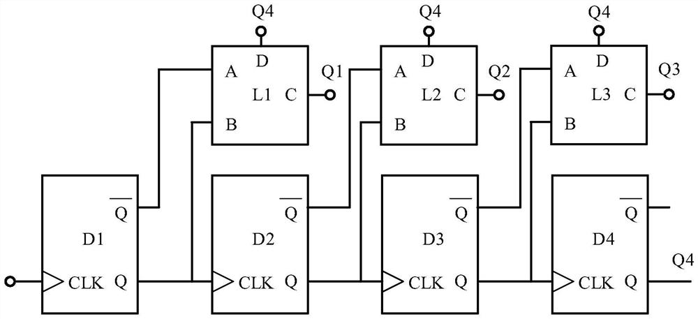
The invention discloses a frequency jitter device and a switching power supply, and relates to the technical field of switching power supplies. The frequency jitter device comprises an oscillator circuit and a frequency jitter circuit. Wherein the oscillator circuit comprises a first current source, a first switching circuit and a first charging and discharging circuit; the first switching circuit controls the first current source to charge the first charging and discharging circuit and controls the first charging and discharging circuit to discharge at a constant current so as to generate a clock signal; the frequency jitter circuit comprises a frequency dividing circuit, a second switching circuit and a second charging and discharging circuit; the frequency dividing circuit carries out frequency halving on the clock signal and outputs a frequency dividing signal to control the second switching circuit; and the second switching circuit controls the second charging and discharging circuit to charge and discharge according to the frequency division signal to realize frequency jitter. Therefore, frequency jitter can be simply realized, peak current and harmonic waves generated by the capacitor/inductor can be well eliminated, and EMI (Electro-Magnetic Interference) can be effectively reduced.

Description

technical field [0001] The invention relates to the technical field of switching power supplies, in particular to a frequency shaking device and a switching power supply. Background technique [0002] Switching power supply plays a vital role in electronic design. As the input of any chip, the stability of its working state will affect the working stability of the whole system. [0003] The switching power supply system usually adopts the control method of pulse width modulation (PWM, Pulse Width Modulation), and the switching frequency is continuously increasing. Its high-frequency switching waveform contains a large number of harmonic components. Spikes, voltage changes in capacitance and parasitic capacitances cause electric fields to form higher current spikes. [0004] Spikes often contain huge harmonic components, which propagate outward through transmission lines and space electromagnetic fields, causing conduction and radiation interference (EMI interference). Such ...

Claims


Application Information

Patent Timeline
Patent Type & Authority Applications(China)
IPC IPC(8): H02M1/12H02M1/44
CPCH02M1/12H02M1/44
Inventor 范建功
Owner NUBIA TECHNOLOGY CO LTD
Why Eureka
Try Eureka