Metal plating equipment

An equipment and metal technology, applied in the field of metal plating equipment, can solve the problems of increased cost, increased enterprise cost, and reduced process efficiency, and achieves the effect of reducing quantity requirements, saving time and cost, and improving process efficiency.

Pending Publication Date: 2022-03-25
新阳硅密(上海)半导体技术有限公司
View PDF6 Cites 0 Cited by
  • Summary
  • Abstract
  • Description
  • Claims
  • Application Information

AI Technical Summary

Problems solved by technology

[0004] 1. Each process uses different equipment, which means that after a certain process is completed, the wafer must be taken out of the equipment, and then put into another equipment for subsequent processes, and so on until all processes are completed, which causes Great waste of time, greatly reduced process efficiency, and more equipment means larger floor space, which undoubtedly increases the cost of the enterprise
[0005] 2. Because each process uses different equipment, and usually each equipment must use a corresponding wafer fixture, and each wafer fixture is driven by a different manipulator, which leads to a waste of space and an increase in cost, and, such The structural design also makes it necessary to frequently switch wafer fixtures during the entire process, increasing the risk of wafer damage and oxidation of the wafer surface, which can easily reduce the electrical performance of the wafer; in addition, for For wafers, the clamping positions of different wafer fixtures have positive and negative tolerances. When making multiple layers, frequent replacement of wafer fixtures may cause uneven stress on the film layer, resulting in warpage of the wafer.
[0006] 3. In some cases, the wafer must undergo subsequent processes within a short period of time after the previous process is completed, but since different processes are carried out in different equipment, this may result in a decline in product performance
For example, copper is easy to oxidize in the air to form an oxide layer. In the prior art, the copper seed layer of the wafer must be taken out of the equipment after completing pre-treatment processes such as acid treatment, and directly exposed to the external environment, and then Enter the subsequent plating equipment to implement the hole filling process, which may cause the secondary oxidation of the copper seed layer, resulting in a decrease in the electrical performance of the wafer

Method used


Image

  • Metal plating equipment
  • Metal plating equipment
  • Metal plating equipment

Examples


Embodiment 1

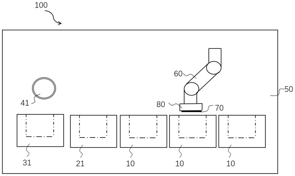
[0073] The present embodiment provides a kind of metal plating equipment 100, comprises a processing chamber 50, is integrated with a plurality of working tanks in the processing chamber 50, and working tank comprises plating tank 10 and process tank, and process tank comprises non-sealed processing process tank and sealed type treatment process tank, specifically, such as figure 1 As shown, in this embodiment, the non-sealed treatment process tank includes the non-sealed pre-treatment process tank 31 , and the sealed treatment process tank includes the sealed pre-treatment process tank 21 .

[0074] The processing chamber 50 is provided with a moving mechanism 60 and a wafer clamp 80, the wafer clamp 80 is used to clamp the wafer 70, the moving mechanism 60 is connected to the wafer clamp 80, the moving mechanism 60 can drive the wafer clamp 80 to move, non-sealed The pre-treatment tank 31 and the plating tank 10 share a wafer holder 80 . In addition, a first wafer holder co...

Embodiment 2

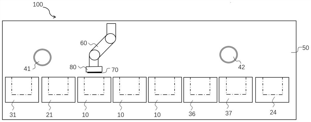
[0088] The present embodiment provides a kind of metal plating equipment 100, comprises a processing chamber 50, is integrated with a plurality of working tanks in the processing chamber 50, and working tank comprises plating tank 10 and process tank, and process tank comprises non-sealed processing process tank and sealed Type treatment process tank. Specifically, such as image 3 As shown, the non-sealed treatment process tank includes a non-sealed pre-treatment process tank 31 and an unsealed post-treatment process tank, and the non-sealed post-treatment process tank includes an EBR treatment process tank 36 and an SRD treatment process tank 37; The process tank includes a sealed pre-treatment process tank 21 and a sealed post-treatment process tank, and the sealed post-treatment process tank includes an annealing treatment process tank 24 .

[0089] The processing chamber 50 is also provided with a moving mechanism 60 and a wafer clamp 80. The wafer clamp 80 is used to cl...

Embodiment 3

[0099] The structure of the metal plating equipment 100 provided by this embodiment is substantially the same as that of Embodiment 2, the difference is that in this embodiment, before the wafer 70 enters the EBR processing tank 36, it is not necessary to unload and unload the wafer from the wafer holder 80, and can Directly driven by the wafer holder 80, it enters the EBR processing tank 36 to perform the EBR processing.

[0100] like Figure 5 and Image 6 As shown, the EBR treatment process tank 36 provided in this embodiment is provided with a spray device 38, and the spray device 38 is provided with a chemical liquid nozzle 381 that is inclined at an angle of 5-15 degrees toward the edge surface of the wafer 70. The spray device 38 is also provided with a number of nitrogen jets 382 and DIW spray ports for jetting nitrogen towards the area within the edge of the wafer 70 .

[0101] After the wafer 70 enters the EBR processing tank 36 with the wafer holder 80, the surfac...


PUM


Abstract

The invention provides metal plating equipment which comprises a treatment chamber, a plurality of working tanks are integrated in the treatment chamber, the working tanks comprise plating tanks and process tanks, and the process tanks comprise non-sealed treatment process tanks and sealed treatment process tanks; a moving mechanism and a wafer clamp are arranged in the treatment chamber, the wafer clamp is used for clamping a wafer, the moving mechanism is used for driving the wafer clamp to move, and the plating tank and all or part of the non-sealed treatment process tanks share one wafer clamp. According to the metal plating equipment provided by the invention, the process tank and the plating tank are integrated in the treatment chamber of the equipment, so that the equipment does not need to be switched in the processes of performing various pretreatment processes and/or post-treatment processes and plating processes (electroplating process and/or chemical plating process) on the wafer, and the production efficiency is improved. The process can enter the next process from the previous process in a short time, so that the time cost is greatly saved, and the process efficiency is improved; in addition, the method also has positive significance in improving the process quality of the wafer.

Description

technical field [0001] The invention relates to the technical field of semiconductor device manufacturing, in particular to a metal plating equipment. Background technique [0002] Semiconductor integrated circuits and other semiconductor devices usually require electroplating or electroless plating processes in the production process to form a variety of metal layers on the surface of the wafer. The metal layers usually include copper, nickel, tin, gold, silver, etc. Among them, electroplating is usually to place the wafer in the electroplating solution, apply the negative electrode of the voltage to the wafer, and apply the positive electrode of the voltage to the anode, and the metal ions in the plating solution are deposited on the surface of the wafer through the action of an electric field. Electroless plating, also known as electroless plating, is a plating method in which metal ions in the plating solution are reduced to metal and deposited on the surface of the wafe...

Claims


Application Information

Patent Timeline
Patent Type & Authority Applications(China)
IPC IPC(8): C25D19/00C25D17/00C25D17/06C25D7/12C25D5/50C25D5/48C25D5/00C23C18/18C23C18/31
CPCC25D17/001C25D7/123C25D17/06C25D5/00C25D5/50C25D5/48C23C18/1632C23C18/1628C23C18/1642C23C18/1689C23C18/1692C23C18/1851C23C18/1872C23C18/31
Inventor 史蒂文·贺·汪林鹏鹏
Owner 新阳硅密(上海)半导体技术有限公司
Why Eureka
Try Eureka