Turbine blade dihedral angle chord width machining device and machining method

A technology of turbine blades and processing devices, applied in metal processing equipment, grinding/polishing safety devices, manufacturing tools, etc., can solve the problems of high processing cost and strong limitations of machine tools

Pending Publication Date: 2022-03-25
GUIYANG AVIC POWER PRECISION CASTING
View PDF0 Cites 0 Cited by
  • Summary
  • Abstract
  • Description
  • Claims
  • Application Information

AI Technical Summary

Problems solved by technology

In this way, the processing cost of machine tools with dihed

Method used


Image

  • Turbine blade dihedral angle chord width machining device and machining method
  • Turbine blade dihedral angle chord width machining device and machining method
  • Turbine blade dihedral angle chord width machining device and machining method

Examples


Embodiment Construction

[0037] The principles and features of the present invention are described below in conjunction with the accompanying drawings, and the examples given are only used to explain the present invention, and are not intended to limit the scope of the present invention.

[0038] In describing the present invention, it is to be understood that the terms "centre", "length", "upper", "lower", "front", "rear", "left", "right", "vertical", The orientation or positional relationship indicated by "horizontal", "top", "inner", "outer", "circumferential", "circumferential" is based on the orientation or positional relationship shown in the drawings, and is only for the convenience of describing this Inventions and simplified descriptions do not indicate or imply that the system or element referred to must have a particular orientation, be constructed, and operate in a particular orientation, and thus should not be construed as limiting the invention.

[0039] In the description of the present...


PUM

PropertyMeasurementUnit
Diameteraaaaaaaaaa
Thicknessaaaaaaaaaa

Abstract

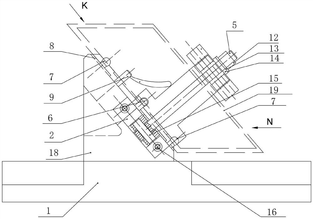
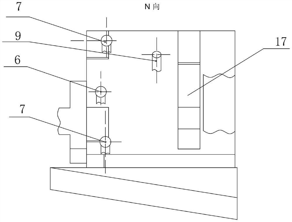
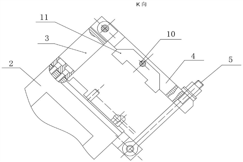
The invention relates to a turbine blade dihedral angle chord width machining device and method. The turbine blade dihedral angle chord width machining device comprises a base, an inclined support is arranged on the base, a supporting column perpendicular to the support is arranged on the support, a connecting rod is horizontally hinged to one end of the supporting column, a swing bolt is arranged at the other end of the connecting rod in a penetrating mode, and the swing bolt is arranged on the base. The other end of the swing bolt is arranged in the support, and positioning balls are arranged on the two sides of the swing bolt. The machining precision of the dihedral angle chord width of the turbine blade can be effectively improved.

Description

technical field [0001] The invention relates to the field of machining turbine blades of aero-engines, in particular to a machining device and a machining method for dihedral angle and chord width of turbine blades. Background technique [0002] At present, the dihedral angle of the guide blade of the aero-engine turbine is processed by the thin-walled positioning of the trailing edge of the blade body. Since the front and rear edge plates of the blade have a certain inclination angle, the radial direction also has an inclination angle. When processing the half-chord width, it is necessary to ensure the relative position between the edge plate and the blade body, and the circumferential direction needs to use the blade in the middle of the blade body as the circumferential positioning point. The current processing methods are all using ordinary fixtures for clamping, and using high-precision five-axis machine tools to process the blades by inverting the angles of the machine...

Claims


Application Information

Patent Timeline
IPC IPC(8): B24B19/14B24B27/00B24B41/06B24B55/02
CPCB24B19/14B24B27/0023B24B41/06B24B55/02
Inventor 张旭洲和秋香韩丹冉振展光程计正康
Owner GUIYANG AVIC POWER PRECISION CASTING
Why Eureka
Try Eureka