
Rapid copper wire cutting device

A rapid cutting and copper wire technology, applied in the field of copper wire cutting, can solve the problems of low copper wire cost, low efficiency, cutting efficiency affected by tools, etc., and achieve the effect of ensuring cutting efficiency

Pending Publication Date: 2022-03-25
徐州固城铜业有限责任公司
View PDF0 Cites 0 Cited by
  • Summary
  • Abstract
  • Description
  • Claims
  • Application Information

AI Technical Summary

Problems solved by technology

[0002] At present, copper has good conductivity, and the cost of copper wire is low, and it is widely produced, so it replaces silver as a conductor. Copper wire is widely used in industrial filtration, petroleum, chemical, printing, cable and other industries. With the development of society, copper wire The demand for copper wire has also increased. When the copper wire is packaged, it needs to be cut for each package. The efficiency of manual cutting is very low. Therefore, it is necessary to use mechanical equipment to quickly cut the copper wire.
[0003] There are also more inconveniences when cutting with mechanical equipment. Different thickness copper wires require different cutting knives. In order to ensure the complete cutting of thin steel wires, sharper and sharper knives need to be used. Thick steel wires need larger hardness and A tool with a slightly larger thickness will affect the cutting efficiency when changing the cutting wire.

Method used


Image

  • Rapid copper wire cutting device
  • Rapid copper wire cutting device
  • Rapid copper wire cutting device

Examples


Embodiment Construction

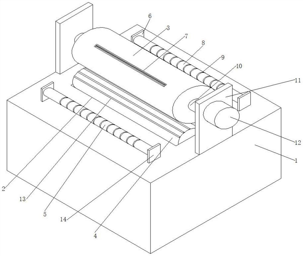
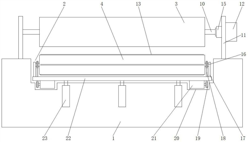
[0027] see Figure 1-4 , the present invention provides a technical solution: a copper wire rapid cutting device, including a support 1, a roller groove 2, an upper roller 3, a lower roller 4 and a leading roller 5; the roller groove 2 is arranged laterally on the support 1, and the roller groove 2 is located laterally in the middle of the surface of the support 1;

[0028] A lifting plate 22 is arranged horizontally below the inside of the roller groove 2, and the lifting plate 22 is parallel to the bottom of the roller groove 2. A first electric push rod 23 is vertically embedded in the support 1 below the lifting plate 22. There are three push rods 23, and the top of the first electric push rod 23 is fixed on the lower surface of the lifting plate 22, and the two sides of the surface of the lifting plate 22 are vertically fixed with the second side plate 17, and the lower roller 4 passes through The second rotating rod 16 is rotatably installed between the second side plat...


PUM


Abstract

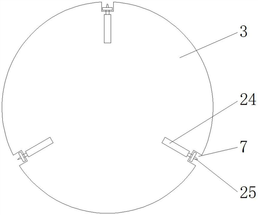
The invention relates to the technical field of copper wire cutting, and discloses a rapid copper wire cutting device which comprises a support, a roller groove, an upper rotating roller, a lower rotating roller and a front guide roller. The roller groove is transversely formed in the surface of the support and is transversely located in the middle of the surface of the support, a lifting plate is transversely arranged on the lower portion of the interior of the roller groove and is parallel to the bottom of the roller groove, and three first electric push rods are vertically embedded into the portion, below the lifting plate, of the interior of the support. The upper rotating roller with the three cutter grooves is located above the lower rotating roller, when cutting is needed, the lower rotating roller pushes a copper wire to the bottom of the upper rotating roller, the thicknesses of the cutters fixed in the cutter grooves are sequentially increased, and sharp thin copper wires with small thickness can be selected to be cut according to the thickness of the steel wire; in addition, the front guide roller and the rear guide roller can guide the multiple copper wires at a time, the multiple copper wires can be cut, and the cutting efficiency of the copper wires is guaranteed.

Description

technical field [0001] The invention relates to the technical field of copper wire cutting, in particular to a rapid copper wire cutting device. Background technique [0002] At present, copper has good conductivity, and the cost of copper wire is low, and it is widely produced, so it replaces silver as a conductor. Copper wire is widely used in industrial filtration, petroleum, chemical, printing, cable and other industries. With the development of society, copper wire The demand for copper wire has also increased. When the copper wire is packaged, it needs to be cut for each package. The efficiency of manual cutting is very low, so it is necessary to use mechanical equipment to quickly cut the copper wire. [0003] There are also more inconveniences when cutting with mechanical equipment. Different thickness copper wires require different cutting knives. In order to ensure the complete cutting of thin steel wires, sharper and sharper knives need to be used. Thick steel wir...

Claims


Application Information

Patent Timeline
Patent Type & Authority Applications(China)
IPC IPC(8): B21F11/00
CPCB21F11/00
Inventor 戚峻豪
Owner 徐州固城铜业有限责任公司
Learn More