Rotary electric machine control device
A technology for rotating electrical machines and control devices, which is applied in motor control, AC motor control, control systems, etc., and can solve problems such as over-output
- Summary
- Abstract
- Description
- Claims
- Application Information
AI Technical Summary
Problems solved by technology
Method used
Image
Examples
no. 1 approach
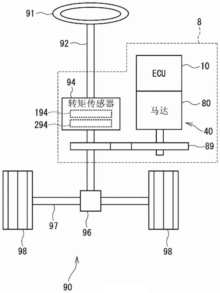
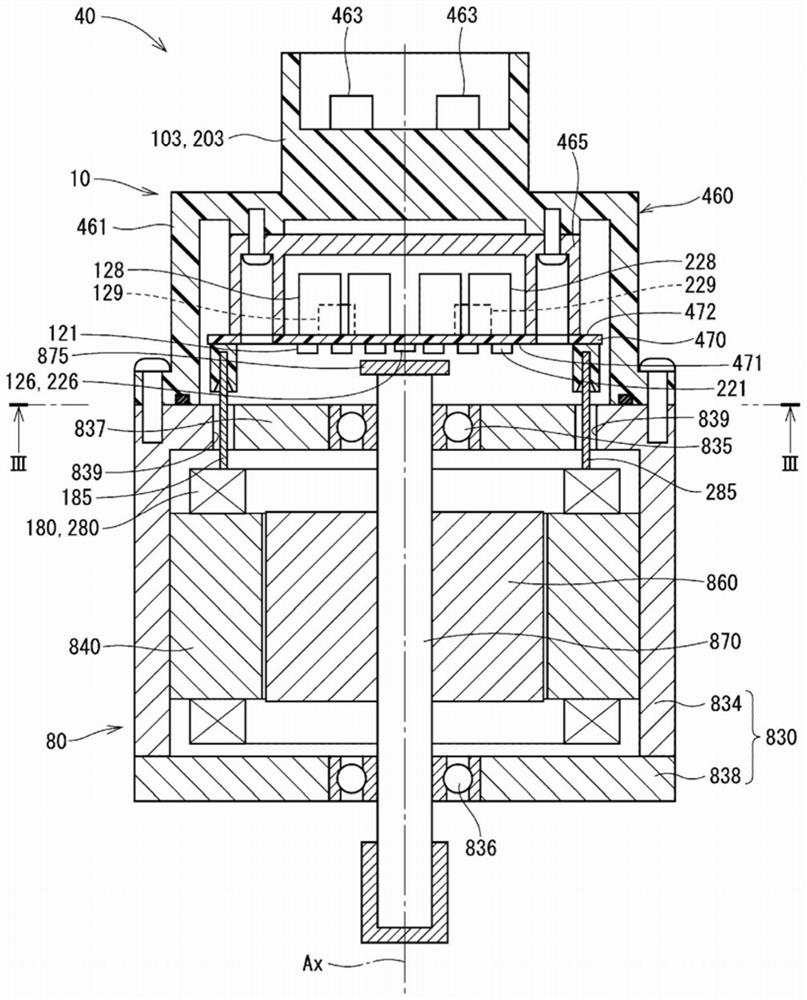
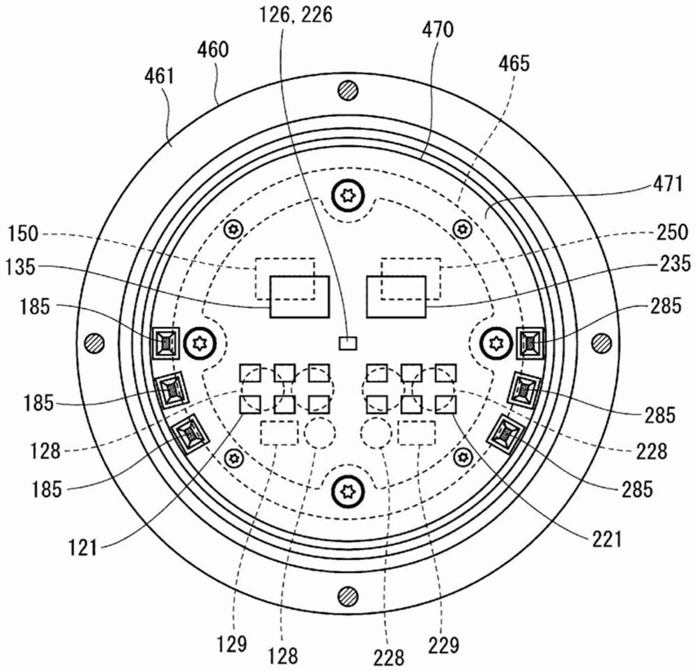
[0031] Figure 1 to Figure 13 shows the first embodiment. Such as figure 1 As shown, ECU 10 as a rotary electric machine control device controls the drive of motor 80 as a rotary electric machine, and is applied together with motor 80 to electric power steering 8 as a steering device for assisting steering operations of a vehicle, for example. figure 1 The structure of the steering system 90 provided with the electric power steering apparatus 8 is shown. The steering system 90 includes a steering wheel 91 as a steering member, a steering shaft 92 , a pinion 96 , a rack shaft 97 , wheels 98 , the electric power steering 8 , and the like.
[0032] The steering wheel 91 is connected to a steering shaft 92 . A torque sensor 94 for detecting steering torque is provided on the steering shaft 92 . The torque sensor 94 has the 1st sensor part 194 and the 2nd sensor part 294, and the sensor which can each detect the failure detection of itself is made into duplication. A pinion ge...
no. 2 approach
[0122] Figure 14 ~ Figure 16 Shows the second embodiment. In the present embodiment, the drive mode selection process is different from the above-described embodiments, and therefore the description will focus on this point. In the present embodiment, even when shifting to the independent drive mode or the single-system drive mode, if the coordinated drive mode can be restored, the coordinated drive mode is restored.
[0123] based on Figure 14 The flow chart of the figure describes the drive mode selection process of this embodiment. The processing of S201, S202 and Figure 8 The processing of S101 and S102 in the same. When the communication between microcomputers is abnormal, it moves to S206. In addition, when the inter-microcomputer communication is normal and the cooperative driving is in progress, the process moves to S204 and the cooperative driving is continued, and when the cooperative driving is not in progress, the process moves to S203.
[0124] In S203, t...
other Embodiment approach
[0132] In the above-mentioned embodiment, the monitored abnormality is an uncoordinated abnormality, and the uncoordinated abnormality includes an inter-microcomputer communication abnormality and a synchronization abnormality. In other embodiments, either one of the inter-microcomputer communication abnormality or synchronization abnormality may be regarded as an uncoordinated abnormality. In addition, the abnormality to be monitored may be an abnormality other than an uncoordinated abnormality. In the above-described embodiments, the other system monitoring information is other system relay information. In other embodiments, other system monitoring information may use information other than other system relay information capable of monitoring the status of other systems. In the above embodiments, other system monitoring circuits are used to directly acquire other system relay information. In other implementations, other system monitoring information may also be obtained th...
PUM
 Abstract
Description
Claims
Application Information
 - R&D Engineer
- R&D Manager
- IP Professional
- Industry Leading Data Capabilities
- Powerful AI technology
- Patent DNA Extraction
Browse by: Latest US Patents, China's latest patents, Technical Efficacy Thesaurus, Application Domain, Technology Topic, Popular Technical Reports.
© 2024 PatSnap. All rights reserved.Legal|Privacy policy|Modern Slavery Act Transparency Statement|Sitemap|About US| Contact US: help@patsnap.com


