Light guide plate capable of improving brightness
A light guide plate and brightness technology, applied in light guides, optics, optical components, etc., can solve the problems of no light guide, reduced light output brightness of the light output end surface, large light loss, etc., to achieve the effect of improving light output brightness and reducing light loss
- Summary
- Abstract
- Description
- Claims
- Application Information
AI Technical Summary
Problems solved by technology
Method used
Image
Examples
Embodiment 1
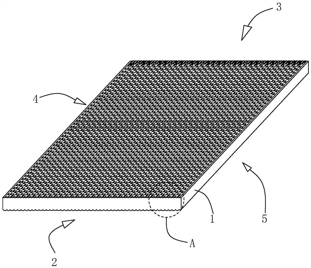
[0051] refer to figure 1 , a light guide plate for improving brightness, comprising a light guide plate body 1, the two end faces of the light guide plate body 1 are a light incident end face 2 and a light output end face 3, and the two surfaces in the thickness direction of the light guide plate body 1 are respectively a reflective surface 4 and a light output face 5. Wherein, the light incident end surface 2 is the incident end of the light source, the reflective surface 4 is used for reflecting light, and the light emitting surface 5 is used for refracting light and emitting light.
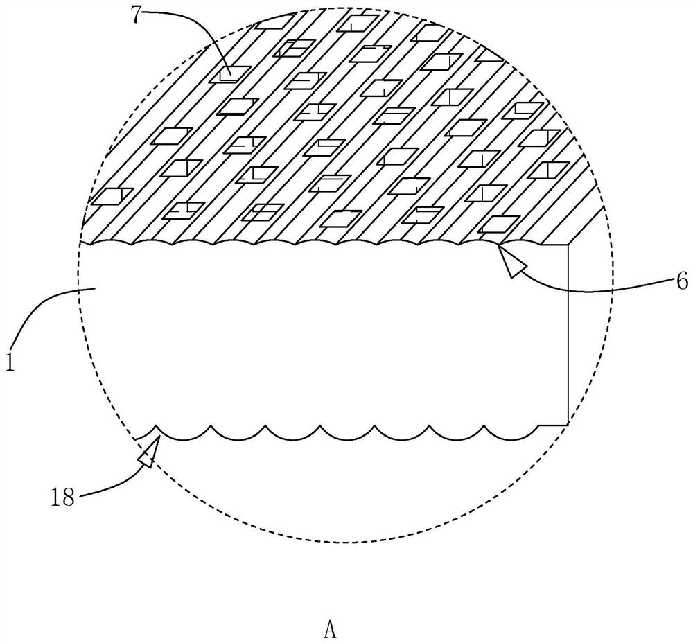
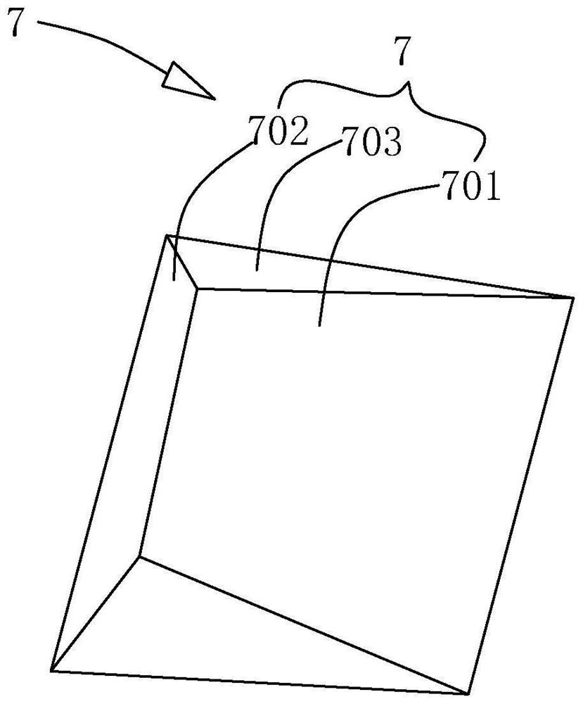
[0052] refer to figure 2 The reflective surface 4 of the light guide plate body 1 is provided with a reflective cutout 6 , and the reflective cutout 6 is provided through from the light incident end surface 2 to the light exit end surface 3 along the incident direction of the light source. The reflective groove 6 is an arc-shaped groove. Specifically, the groove walls of the reflective groov...
Embodiment 2
[0063] refer to Figure 7 , different from Embodiment 1, a light-receiving surface 8 is also provided between the light-receiving surface 701 and the back-light surface 702, and an included angle is formed between the connection between the light-receiving surface 8 and the opposite sides of the light-receiving surface 701, and the range of the included angle is 100° °-160°, the angle range formed between the light-receiving surface 8 and the reflecting surface 4 is 0°-60°. At this time, the light-receiving surface 8 tends to be inclined towards the light-incident end surface 2, so that the light-receiving surface 701 is increased area, so as to receive more light and reflect more light to the light-emitting surface 5, so as to increase the reflection range of light on the dot 7.
[0064] refer to Figure 8 , when the dots 7 are orthographically projected on the reflective surface 4, the orthographic projection surface 11 of the light receiving surface is an isosceles trapezo...
Embodiment 3
[0068] refer to Figure 10 , and the difference from Embodiment 1 is that the dot 7 is a dot depression that is depressed inside the light guide plate body 1. Specifically, the light-receiving surface 701 is a plane, and the backlight surface 702 is a curved surface, and the backlight surface 702 is along the circumferential direction of the light-receiving surface 701. set, and the backlight surface 702 transitions from the reflective surface 4 to the light-facing surface 701 in a circular arc along the height direction of the dots 7 , and is recessed toward the inside of the light guide plate body 1 . In addition, the light-receiving surface 701 is inclined from the light-incident end surface 2 to the light-emitting end surface 3 toward the end away from the reflection surface 4 , and the angle between the light-reception surface 701 and the reflection surface 4 ranges from 0° to 70°.
[0069] Such as Figure 11 As shown, when the dots 7 are orthographically projected on the ...
PUM
| Property | Measurement | Unit |
|---|---|---|
| angle | aaaaa | aaaaa |
Abstract
Description
Claims
Application Information
 - R&D Engineer
- R&D Manager
- IP Professional
- Industry Leading Data Capabilities
- Powerful AI technology
- Patent DNA Extraction
Browse by: Latest US Patents, China's latest patents, Technical Efficacy Thesaurus, Application Domain, Technology Topic, Popular Technical Reports.
© 2024 PatSnap. All rights reserved.Legal|Privacy policy|Modern Slavery Act Transparency Statement|Sitemap|About US| Contact US: help@patsnap.com


