Modal test suspension device and modal test system

A modal test and suspension device technology, which is applied in the direction of measuring devices, testing of mechanical components, testing of machine/structural components, etc., can solve the problems of small application range and complicated operation of air springs, so as to avoid safety accidents and improve convenience Performance and reliability, and the effect of improving safety

Pending Publication Date: 2022-03-22
BEIJING RES INST OF MECHANICAL & ELECTRICAL TECH
View PDF0 Cites 0 Cited by
  • Summary
  • Abstract
  • Description
  • Claims
  • Application Information

AI Technical Summary

Problems solved by technology

[0005] In view of the above-mentioned analysis, the present invention aims to provide a modal test suspension device and a modal test system to solve the problems of complex air spring operation and small application range in the existing modal test boundary condition simulation

Method used


Image

  • Modal test suspension device and modal test system
  • Modal test suspension device and modal test system
  • Modal test suspension device and modal test system

Examples


Embodiment 1

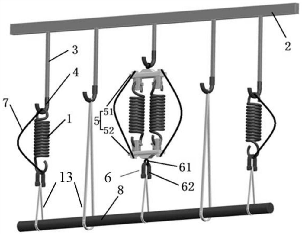
[0052] see figure 1 , a specific embodiment of the present invention discloses a modal test suspension device. The modal test suspension device of this embodiment is used for high-precision parameter measurement of 3-5 Hz aerospace product modal tests with long length (more than 20 meters), larger volume and heavier weight (more than 30 tons).

[0053] The modal test suspension device of this embodiment includes: a suspension assembly and a test piece 8 connected to the suspension assembly; the suspension assembly includes a plurality of steel springs 1, and the technical parameters of the steel springs 1 are based on the test piece 8 weight and fundamental frequency to determine.

[0054] During implementation, the effect of modal test suspension device among the present invention is to make the test piece 8 of modal test be in suspension state, and simulate free-free boundary condition, measure the structural modal parameter of test piece 8 under free-free state .

[0055...

Embodiment 2

[0087]Another embodiment of the present invention provides a suspension method for carrying out a modal test using the suspension device of Embodiment 1, which specifically includes the following steps:

[0088] Design the technical parameters of the steel springs included in the suspension assembly, said technical parameters including the wire diameter of the steel spring, the outer diameter of the spring, the direction of rotation, the elongation length and the bearing capacity;

[0089] According to the determined technical parameters, a suspension assembly is used to suspend the test piece so that the test piece is in a free-free boundary condition.

[0090] In the above specific method, the design method of the technical parameters is to determine the technical parameters of the spring according to the axial deformation of the steel spring, wherein the calculation formula of the axial deformation is:

[0091]

[0092] In the above formula:

[0093] λ is the amount of ...


PUM


Abstract

The invention relates to a modal test suspension device and a modal test system, belongs to the technical field of modal test parameter measurement, and solves the problems of complex operation and small application range of an air spring in modal test boundary condition simulation in the prior art. A modal test suspension device comprises: a suspension assembly; the suspension assembly comprises a plurality of steel springs, and the technical parameters of the steel springs are determined according to the weight and fundamental frequency of the test piece; the multiple steel springs are arranged in parallel, and at least one set of steel springs is formed by connecting the multiple steel springs in parallel. The device also comprises a crane crossbeam, the crane crossbeam is connected with a plurality of lifting chains, and each steel spring and each group of steel springs respectively suspend the test piece on the lifting chains through lifting hooks. According to the invention, the suspension assembly is arranged and the test piece is suspended on the suspension assembly, so that high-precision parameter measurement of a modal test of the test piece with relatively large size, weight and low fundamental frequency can be facilitated.

Description

technical field [0001] The invention relates to the technical field of modal test parameter measurement, in particular to a modal test suspension device and a modal test system. Background technique [0002] At present, the rapid development of aerospace technology has put forward higher requirements for modal test technology. Larger volume, larger mass, low frequency, and ultra-low frequency modal measurement requirements are becoming more prominent. In order to accurately provide modal parameters for the development and design of aerospace products, it is necessary to excite the test piece through modal tests to measure the dynamic characteristics, natural frequency, mode shape and damping parameters of the structure. In the modal tests at home and abroad, the test piece should be in a completely free state without being affected by additional boundary constraints. Therefore, in order to obtain the free-free state of the test piece, most of the suspension is used to simul...

Claims


Application Information

Patent Timeline
Patent Type & Authority Applications(China)
IPC IPC(8): G01M13/00
CPCG01M13/00
Inventor 丁宁王大鹏任杰安李乃田秦红兴
Owner BEIJING RES INST OF MECHANICAL & ELECTRICAL TECH
Why Eureka
Try Eureka