High-altitude long-endurance unmanned aerial vehicle with foldable telescopic wings
A folding wing and long-endurance technology, applied in the aviation field, can solve the problems of unmanned aerial vehicles with too large wingspan, large space occupation, and difficulty in rapid deployment, so as to improve space utilization, reduce occupied volume, and light weight Effect
- Summary
- Abstract
- Description
- Claims
- Application Information
AI Technical Summary
Problems solved by technology
Method used
Image
Examples
specific Embodiment approach 1
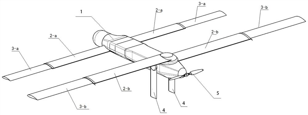
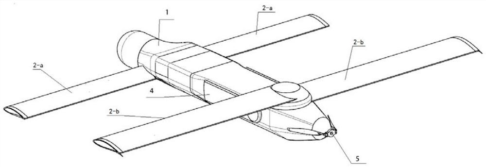
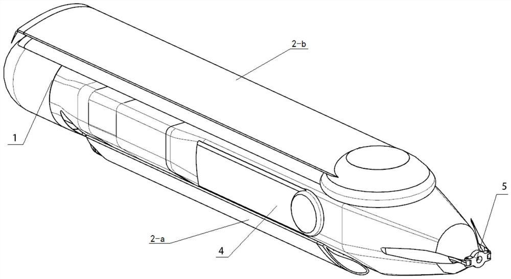
[0041] Specific implementation mode one: combine Figure 1 to Figure 16 Describe this embodiment, a high-altitude long-endurance UAV with foldable and telescopic wings described in this embodiment includes a fuselage 1, two front folding wings 2-a, two rear folding wings 2-b, two A front telescopic wing 3-a, two rear telescopic wings 3-b, two folding empennages 4, two folding propeller blades 5, a plurality of folding mechanisms and a plurality of telescopic mechanisms, the two sides of the fuselage 1 front respectively A front folding wing 2-a is symmetrically arranged, and a front telescopic wing 3-a is inserted into the outer end of the front folding wing 2-a, and a rear folding wing 2-b is respectively symmetrically arranged on both sides of the top of the rear part of the fuselage 1 , the outer end of the rear folding wing 2-b is inserted with a rear telescopic wing 3-b, a folding empennage 4 is symmetrically arranged on both sides of the rear of the fuselage 1, and two f...
specific Embodiment approach 2
[0045] Specific implementation mode two: combination Figure 1 to Figure 16 Describe this embodiment, the folding mechanism described in this embodiment includes a spring hook 7, a tension spring 8, a steel wire 9, a pulley 10, a round hole shaft seat 11-a, a semicircle hole shaft seat 11-b and a rotating shaft 16, and the spring hook 7 , pulley 10, round hole shaft seat 11-a, and semicircular hole shaft seat 11-b are all fixedly connected on the fuselage 1, and the inner side end of rotating shaft 16 is inserted on the round hole shaft seat 11-a, and the outer side end of rotating shaft 16 Inserted on the semicircular hole shaft seat 11-b, and the rotating shaft 16 is rotationally connected with the round hole shaft seat 11-a and the semicircular hole shaft seat 11-b, and one end of the steel wire 9 is fixed on the side wall of the rotating shaft 16, and the steel wire 9 The other end of the other end is connected with an end of the tension spring 8 after bypassing the pulley...
specific Embodiment approach 3
[0049] Specific implementation mode three: combination Figure 1 to Figure 16 Describe this embodiment, the folding mechanism in this embodiment also includes a shaft cover 12, the shaft cover 12 is fixed on the semi-circular hole shaft seat 11-b to form a complete round hole shaft seat, and is rotatably connected with the outer end of the rotating shaft 16 . Other compositions and connection methods are the same as those in the second embodiment.
PUM
 Abstract
Description
Claims
Application Information
 - R&D
- Intellectual Property
- Life Sciences
- Materials
- Tech Scout
- Unparalleled Data Quality
- Higher Quality Content
- 60% Fewer Hallucinations
Browse by: Latest US Patents, China's latest patents, Technical Efficacy Thesaurus, Application Domain, Technology Topic, Popular Technical Reports.
© 2025 PatSnap. All rights reserved.Legal|Privacy policy|Modern Slavery Act Transparency Statement|Sitemap|About US| Contact US: help@patsnap.com


