Series balloon catheter
A balloon catheter and balloon technology, which is applied in the field of series balloon catheters, can solve the problems of no handle at the end of the balloon catheter, inconvenient operation for doctors, and inconvenient movement of the balloon to the target position, etc., so as to simplify the operation process, Simple operation effect
- Summary
- Abstract
- Description
- Claims
- Application Information
AI Technical Summary
Problems solved by technology
Method used
Image


Examples
specific Embodiment approach 1
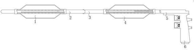
[0038] Specific implementation mode one: please refer to Figure 1-11 , the present invention provides a technical solution: a series balloon catheter, comprising: a first balloon structure 1, a second balloon structure 4 and a handle structure 6;
[0039] The right side of the first balloon structure 1 is equipped with an adjustment rod 2, and the side of the adjustment rod 2 away from the first balloon structure 1 is installed with a communication tube 3, and the right side of the communication tube 3 is installed with a second balloon structure 4 , and the side of the second balloon structure 4 away from the connecting tube 3 is installed with an air inlet end 5, and the bottom of the air inlet end 5 is installed with a handle structure 6;
[0040] The second balloon structure 4 works in the same way as the first balloon structure 1, and the rear balloon 41 of the second balloon structure 4 is wrapped on the outside of the rear jet tube 42, and the front jet tube 14 is resp...
specific Embodiment approach 2
[0043] Specific embodiment 2: This embodiment is a further limitation of specific embodiment 1. The first balloon structure 1 includes a front balloon 11, a front jet tube 12, an opening 13, a front air tube 14 and a position-limiting gasket 15, and the front Air pipe 14 is placed in the inside of front air injection pipe 12, and the outer surface of front air injection pipe 12 is evenly provided with a plurality of groups of openings 13, and front air pipe 14 is limited by spacer gasket 15 inside front air injection pipe 12.
[0044] Such as Figure 1-2 As shown: the working principle of the first balloon structure 1 is: the gas is ejected from the end of the front air pipe 14, so that the gas enters the inside of the front air injection pipe 12, and the front balloon 11 is lifted up through the opening 13, The front balloon 11 is inflated into an ellipsoid, and the target position is stretched or blocked.
specific Embodiment approach 3
[0045] Specific embodiment three: This embodiment is a further limitation of specific embodiment one. The second balloon structure 4 includes a rear balloon 41, a rear air jet pipe 42 and a rear air pipe 43, and the outer surface of the rear air jet pipe 42 is uniformly opened with multiple Group perforation 13, rear balloon 41 is wrapped on the rear jet pipe 42, rear air pipe 43 end is communicated with rear air connecting pipe 61, and front air pipe 14 end is communicated with front air connecting pipe 62.
[0046] Such as figure 1 and image 3 As shown: the working principle of the second balloon structure 4 is consistent with that of the first balloon structure 1. The rear balloon 41 is placed on the affected area, and the gas enters the inside of the rear jet tube 42 from the end of the rear trachea 43, and the rear jet tube 42 Both sides of the inside of the airtight cavity are sealed by two sets of spacer gaskets 15, so that a closed cavity is formed inside the rear je...
PUM
 Abstract
Description
Claims
Application Information
 - R&D
- Intellectual Property
- Life Sciences
- Materials
- Tech Scout
- Unparalleled Data Quality
- Higher Quality Content
- 60% Fewer Hallucinations
Browse by: Latest US Patents, China's latest patents, Technical Efficacy Thesaurus, Application Domain, Technology Topic, Popular Technical Reports.
© 2025 PatSnap. All rights reserved.Legal|Privacy policy|Modern Slavery Act Transparency Statement|Sitemap|About US| Contact US: help@patsnap.com