


Quick Research
Generate reliable direction feasibility study reports for your R&D in just a few steps.

Technical Q&A
Discover and master advanced knowledge NOW. Basics, ideas, possibilities, all at once.

Find Solutions
As an expert in R&D theories, this can generate solutions to your technical problems instantly.

Evaluate Feasibility
Analyze your overall solution with one click, know your potential R&D risks in advance.

Monitor Landscape
Get weekly tech updates, stay abreast of the latest tech innovations and key insights.
Humidity adjusting system
A technology of humidity regulation and heat exchanger, which is applied in the direction of air conditioning system, high-efficiency regulation technology, heating and ventilation control system, etc. It can solve the problems that the dehumidification/humidification capacity of the adsorption wheel cannot be improved to the maximum extent, and achieve high-efficiency performance, The effect of system loop optimization
- Summary
- Abstract
- Description
- Claims
- Application Information
AI Technical Summary
Problems solved by technology
Method used
Image


Examples
Embodiment 1
[0044] A humidity conditioning system comprising:
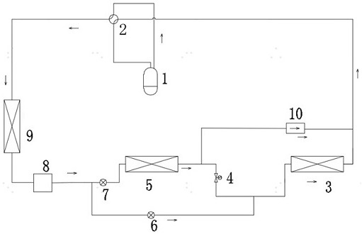
[0045] The compressor 1, the four-way valve 2, the first heat exchanger 3, the second heat exchanger 5, the throttling element 7, the third heat exchanger 9, the third heat exchanger 9 and the four-way valve are sequentially connected through the refrigerant pipeline. Through valve 2 connection;
[0046] The valve unit is used to switch to the state in which the first heat exchanger 3 and the second heat exchanger 5 are connected in series when the four-way valve 2 is switched to the cooling state. The first heat exchanger 3 and the second heat exchanger 5 is a condenser, and the third heat exchanger 9 is an evaporator;
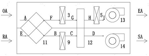
[0047] Total heat exchanger 11;
[0048] Adsorption runner 12;
[0049] The exhaust fan 13 is used to discharge the indoor return air RA through the total heat exchanger 11, the first heat exchanger 3, the adsorption runner 12 and the second heat exchanger 5 in sequence;
[0050] The air supply fan 14 is...
Embodiment 2
[0104] The difference between this embodiment and Embodiment 1 is that the valve unit of this embodiment lacks the third on-off element 6 .
[0105] The valve unit is used to switch to the state where the refrigerant flows through the second heat exchanger 5 and does not flow through the first heat exchanger 3 when the four-way valve 2 is switched to the heating state. The first heat exchanger 3 and the second heat exchanger The heat exchanger 5 is an evaporator, and the third heat exchanger 9 is a condenser.
[0106] Specifically, the valve unit includes:
[0107] The first on-off element 4 is located between the first heat exchanger 3 and the second heat exchanger 5;
[0108] The second on-off element 10, one end of the second on-off element 10 is connected between the second heat exchanger 5 and the first on-off element 4, and the other end of the second on-off element 10 is connected to the four-way valve 2 and the first on-off element 4. Between one heat exchanger 3;
...
PUM
 Abstract
Description
Claims
Application Information
 - R&D Engineer
- R&D Manager
- IP Professional
- Industry Leading Data Capabilities
- Powerful AI technology
- Patent DNA Extraction
Browse by: Latest US Patents, China's latest patents, Technical Efficacy Thesaurus, Application Domain, Technology Topic, Popular Technical Reports.
© 2024 PatSnap. All rights reserved.Legal|Privacy policy|Modern Slavery Act Transparency Statement|Sitemap|About US| Contact US: help@patsnap.com