


Quick Research
Generate reliable direction feasibility study reports for your R&D in just a few steps.

Technical Q&A
Discover and master advanced knowledge NOW. Basics, ideas, possibilities, all at once.

Find Solutions
As an expert in R&D theories, this can generate solutions to your technical problems instantly.

Evaluate Feasibility
Analyze your overall solution with one click, know your potential R&D risks in advance.

Monitor Landscape
Get weekly tech updates, stay abreast of the latest tech innovations and key insights.
Air-raid shelter backfilling and plugging device and construction method thereof
A plugging device and air-raid shelter technology, which is applied in filling, artificial islands, water conservancy projects, etc., can solve problems such as difficult to reinforce the plugging device, high lateral pressure, and difficulty in resisting lateral pressure with a single formwork, so as to save the cost of plugging, The effect of increasing strength
- Summary
- Abstract
- Description
- Claims
- Application Information
AI Technical Summary
Problems solved by technology
Method used
Image

Examples
Embodiment 1
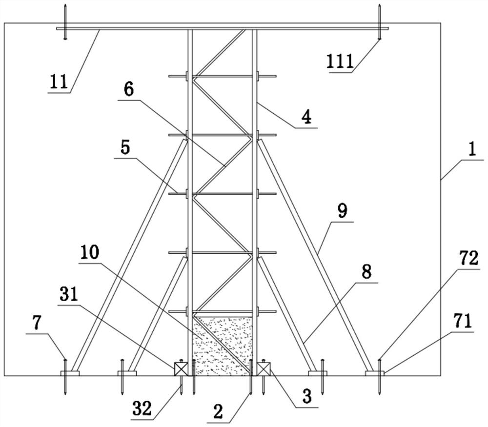
[0037] This embodiment provides a kind of air-raid shelter backfill sealing device and its construction method, such as Figure 1-2 , this air-raid shelter backfill sealing device includes a cave body 1, a first peg 2 is arranged on the inner side of the lower end of the cave body 1, a positioning assembly 3 is arranged on the lower end of the interior of the cave body 1, and the inside of the cave body 1 passes through the first peg 2 and the positioning component 3 are movably connected with a formwork 4, the side wall of the first peg 2 is fitted and connected with the inner wall of the formwork 4, the side wall of the formwork 4 is provided with pull bolts 5, and the inner wall of the formwork 4 is provided with an angle steel skeleton 6, The upper end of the hole body 1 is fitted with an angle steel bracket 11, the lower end of the angle steel bracket 11 is fitted and connected with the template 4 and the angle steel skeleton 6, the upper end of the angle steel bracket 11 ...
Embodiment 2
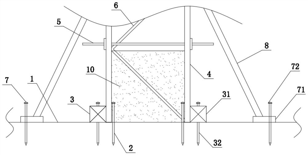
[0040] refer to figure 2 , on the basis of Embodiment 1, in order to achieve the purpose of stabilizing the position of the lower end of the formwork 4, this embodiment innovatively designs the positioning assembly 3, specifically, the positioning assembly 3 includes wooden squares 31 and second pegs 32, wooden squares 31 is arranged inside the hole body 1, the side wall of the wooden square 31 is connected with the formwork 4, the second peg 32 is plugged into the upper end of the wooden square 31, and the lower end of the second peg 32 penetrates through the wooden square 31 and is inserted into the The interior of Cave 1.
[0041] By using the second pegs 32 to fix the position of the wooden cube 31, so that the side wall of the wooden cube 31 is attached to the formwork 4, the positioning component 3 can be used to stabilize the position of the lower end of the formwork 4.
[0042] refer to figure 1 , in order to achieve the purpose of improving the stability of the low...
Embodiment 3
[0047] refer to figure 2 In this embodiment, on the basis of Embodiment 1, in order to achieve the purpose of stabilizing the positions of the first support column 8 and the second support column 9, the installation assembly 7 of this embodiment has been innovatively designed, specifically, the installation assembly 7 includes an installation block 71 and the third peg 72, and the installation block 71 is fixedly connected to the lower ends of the first support column 8 and the second support column 9 respectively, and the lower end of the installation block 71 is fitted and connected with the lower end inside the hole body 1, and the third peg 72 Inserted on the outside of the upper end of the mounting block 71 , the lower end of the third peg 72 passes through the mounting block 71 and is inserted into the lower end of the hole body 1 .
[0048] By using the third peg 72 to fix the position of the mounting block 71, the mounting assembly 7 can play a role in stabilizing the...
PUM
 Abstract
Description
Claims
Application Information
 - R&D Engineer
- R&D Manager
- IP Professional
- Industry Leading Data Capabilities
- Powerful AI technology
- Patent DNA Extraction
Browse by: Latest US Patents, China's latest patents, Technical Efficacy Thesaurus, Application Domain, Technology Topic, Popular Technical Reports.
© 2024 PatSnap. All rights reserved.Legal|Privacy policy|Modern Slavery Act Transparency Statement|Sitemap|About US| Contact US: help@patsnap.com