Dredging device for hydraulic engineering construction
A dredging device and water conservancy engineering technology, which is applied to applications, mechanically driven excavators/dredgers, agricultural machinery and tools, etc., can solve problems such as unfavorable driving excavation, dredging treatment at unfavorable river channels, unfavorable sludge cleaning, etc. Achieve the effect of convenient consignment and avoid driving interference
- Summary
- Abstract
- Description
- Claims
- Application Information
AI Technical Summary
Problems solved by technology
Method used
Image
Examples
Embodiment 1
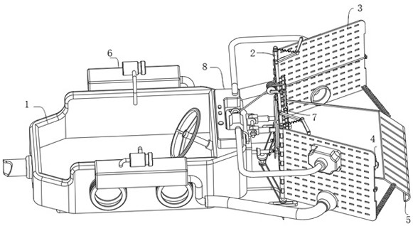
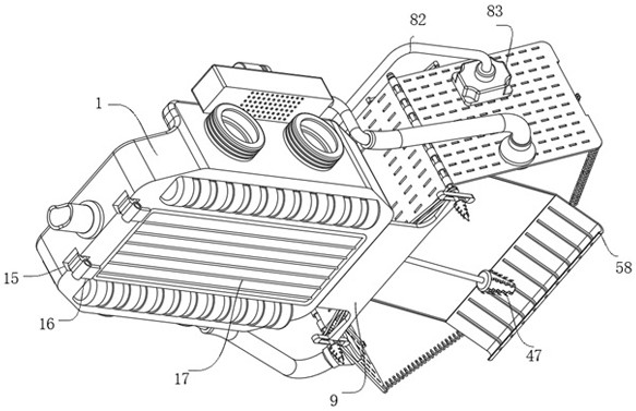
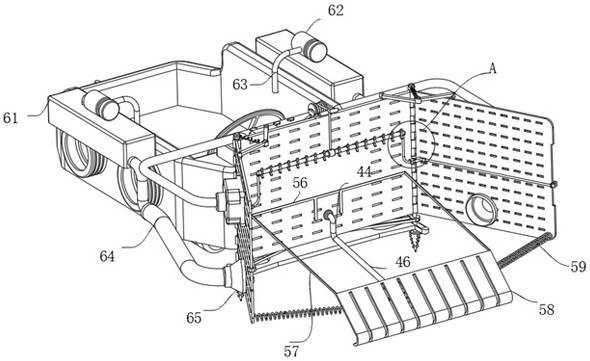
[0032] Embodiment 1, a mounting seat 11 is connected to the top of the hull 1, and two adjustment seats 12 are connected to the mounting seat 11, hydraulic rods 13 are respectively connected to the two adjustment seats 12, and one end of the two hydraulic rods 13 is connected to There is a mounting plate 14, the mounting plate 14 is connected to the outside of the baffle plate 2, the mounting seat 11 here is in the shape of a folded plate, one side is fixed to the top of the hull 1 by bolts, and the other side is connected to the front end of the hull 1 The position is fixed and installed with bolts, and the adjustment rod between the two adjustment seats 12 and the hydraulic rod 13 is used for adjustment, which is convenient for the hydraulic rod 13 to drive the mounting plate 14 to adjust upward or downward, (when not in use , it is necessary to adjust the baffle plate 2 and side plate 3 upwards to facilitate the driving of the hull 1, and to adjust downwards in the case of e...
Embodiment 2
[0033] Embodiment 2, the baffle plate 2 and the side plate 3 in this solution are fixedly connected to the hull 1, the drilling assembly 4 includes a motor 41 connected to the front end of the hull 1, and the outer side of the motor 41 is wrapped with a waterproof cover 42, The output end of the motor 41 is connected with an output shaft 43, and the output shaft 43 is connected with a crank rocker 44, and the crank rocker 44 is designed with a U-shaped transition section and a corner transition section, wherein the horizontally designed shaft section at the corner transition section Part and the output shaft 43 of the motor 41 maintain a uniform horizontal line, and the horizontal position distribution on the corner transition section of the crank rocker 44 is rotatably connected with a rotating clamp seat 45, and the rotating clamp seat 45 is fixedly connected with the two side walls of the baffle plate 2, When the output shaft 43 rotates, the U-shaped transition section is de...
PUM
 Abstract
Description
Claims
Application Information
 - R&D Engineer
- R&D Manager
- IP Professional
- Industry Leading Data Capabilities
- Powerful AI technology
- Patent DNA Extraction
Browse by: Latest US Patents, China's latest patents, Technical Efficacy Thesaurus, Application Domain, Technology Topic, Popular Technical Reports.
© 2024 PatSnap. All rights reserved.Legal|Privacy policy|Modern Slavery Act Transparency Statement|Sitemap|About US| Contact US: help@patsnap.com


