Automatic classification platform for logistics
An automatic classification and platform technology, applied in classification, solid separation, chemical instruments and methods, etc., can solve problems such as inconvenient classification
- Summary
- Abstract
- Description
- Claims
- Application Information
AI Technical Summary
Problems solved by technology
Method used
Image
Examples
Embodiment 1
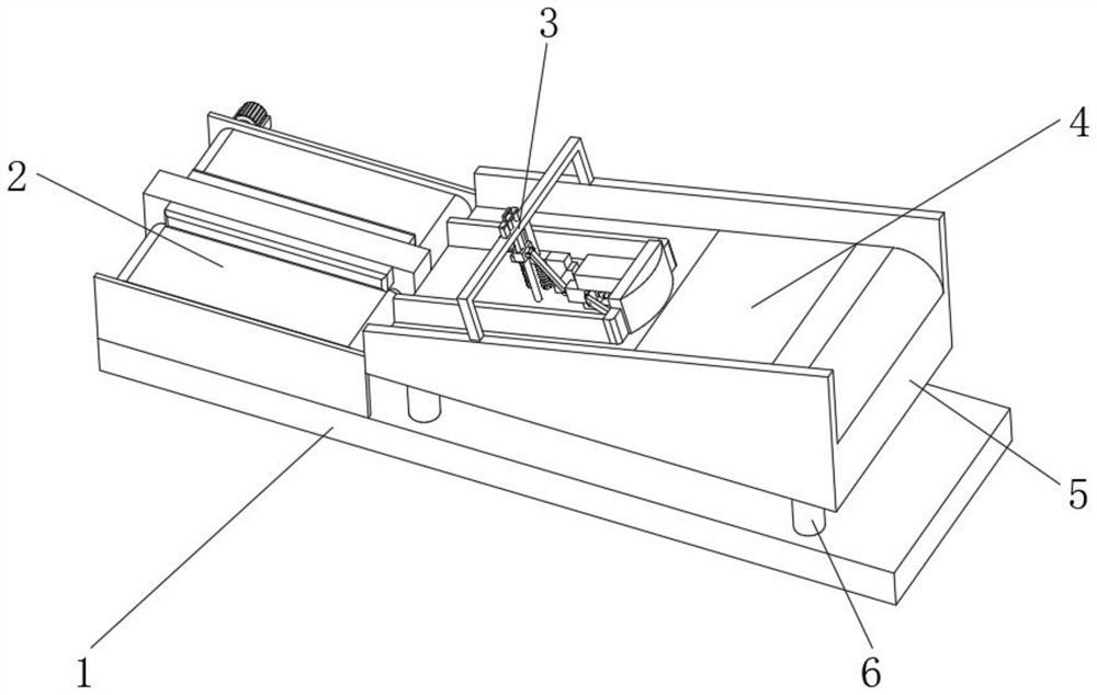
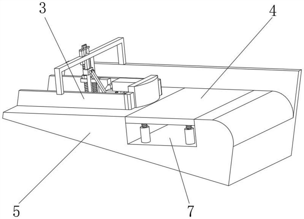
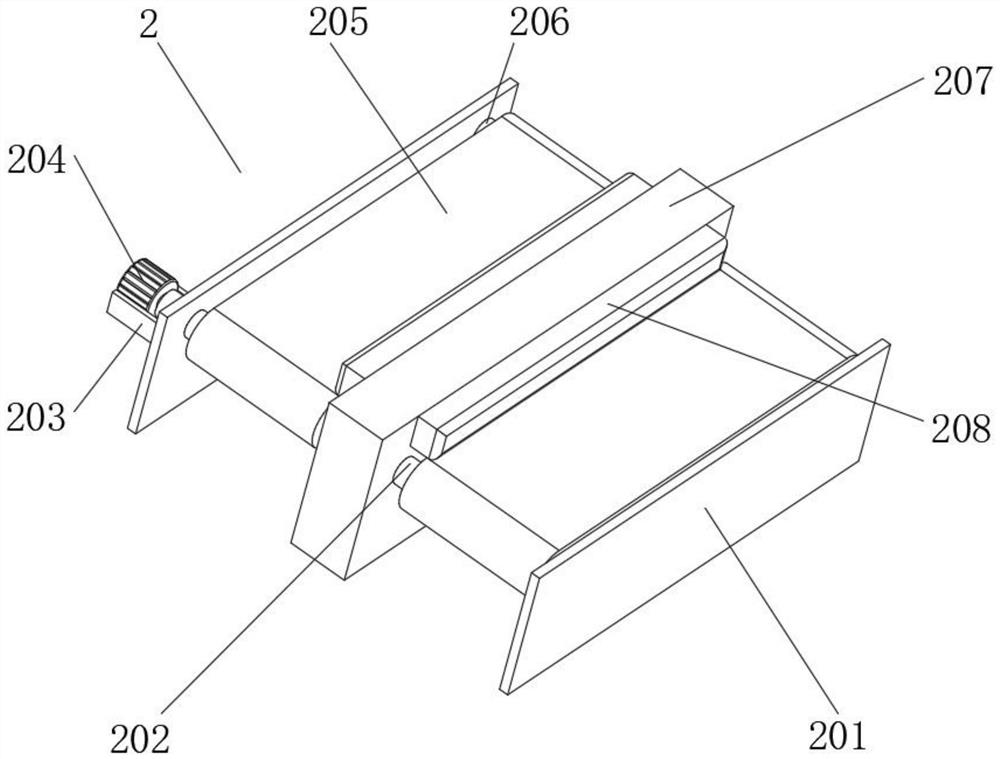
[0029] Embodiment one, by Figure 1-Figure 7 Given, the present invention includes a base 1, a transportation seat 5 is installed above the base 1, and support feet 6 are fixedly connected to the four corners of the transportation seat 5, and the bottom ends of the support feet 6 are fixedly connected to the top of the base 1, and the transportation seat 5 The inside of 5 is equipped with article classification mechanism 3, and the bottom of the inner cavity of transport seat 5 is provided with groove 7, and the inside of groove 7 is equipped with vibration mechanism 4, and the top of base 1 is equipped with classification transportation mechanism 2 near the left side, and classification transportation Mechanism 2 is located on the left side of transport seat 5.
Embodiment 2
[0030]Embodiment 2. On the basis of Embodiment 1, the article classification mechanism 3 includes a vertical block 301 located inside the transport seat 5. The right side of the vertical block 301 is fixedly equipped with a deflector block 302, and the left side of the vertical block 301 is installed with a vertical block. Block 303, a first adjustment unit 304 is installed on the rear side of the installation block 303, a second adjustment unit 306 is installed on the outside of the installation block 303, a U-shaped bar 305 is fixedly installed on the top of the transport seat 5, the first adjustment unit 304 and the second adjustment unit The two adjustment units 306 are both connected to the U-shaped rod 305. The first adjustment unit 304 includes a first fixed rod 3041 located on the rear side of the inner cavity of the installation block 303. The outer side of the first fixed rod 3041 is movably sleeved with a first movable block 3044. The right side of the first movable ...
Embodiment 3
[0032] Embodiment 3, on the basis of Embodiment 1, the vibration mechanism 4 includes a vibration plate 401 located inside the groove 7, the top of the vibration plate 401 is flush with the bottom of the inner cavity of the transport seat 5, and the bottom of the vibration plate 401 is fixed in the middle There is a vibrator 404, and the bottom of the vibrating plate 401 is fixedly connected with support columns 403 near the four corners. The outer side of the support column 403 is movably socketed with a support tube 405, and the bottom of the support tube 405 is fixedly connected with the bottom of the inner cavity of the groove 7. A fourth spring 402 movably socketed with the support column 403 is fixedly connected between the support cylinder 405 and the vibrating plate 401;
[0033] When the items inside the transport seat 5 are blocked and unable to slide down, first start the vibrating machine 404 to drive the rotation of the vibrating plate 401, and at the same time dri...
PUM
 Abstract
Description
Claims
Application Information
 - R&D
- Intellectual Property
- Life Sciences
- Materials
- Tech Scout
- Unparalleled Data Quality
- Higher Quality Content
- 60% Fewer Hallucinations
Browse by: Latest US Patents, China's latest patents, Technical Efficacy Thesaurus, Application Domain, Technology Topic, Popular Technical Reports.
© 2025 PatSnap. All rights reserved.Legal|Privacy policy|Modern Slavery Act Transparency Statement|Sitemap|About US| Contact US: help@patsnap.com


