Drying equipment for production of hydroxypropyl methyl cellulose
A technology of hydroxypropyl methylcellulose and drying equipment, which is applied in drying chambers/containers, drying solid materials, and dry cargo handling, etc., which can solve the problem of long drying time, which is not conducive to the normal production process, and the drying effect is difficult to meet expectations Requirements and other issues to achieve the effect of improving the drying effect
- Summary
- Abstract
- Description
- Claims
- Application Information
AI Technical Summary
Problems solved by technology
Method used
Image
Examples
Embodiment 1
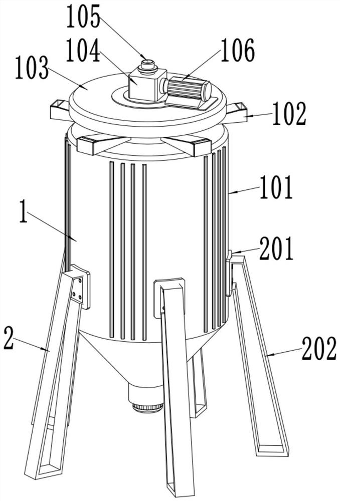
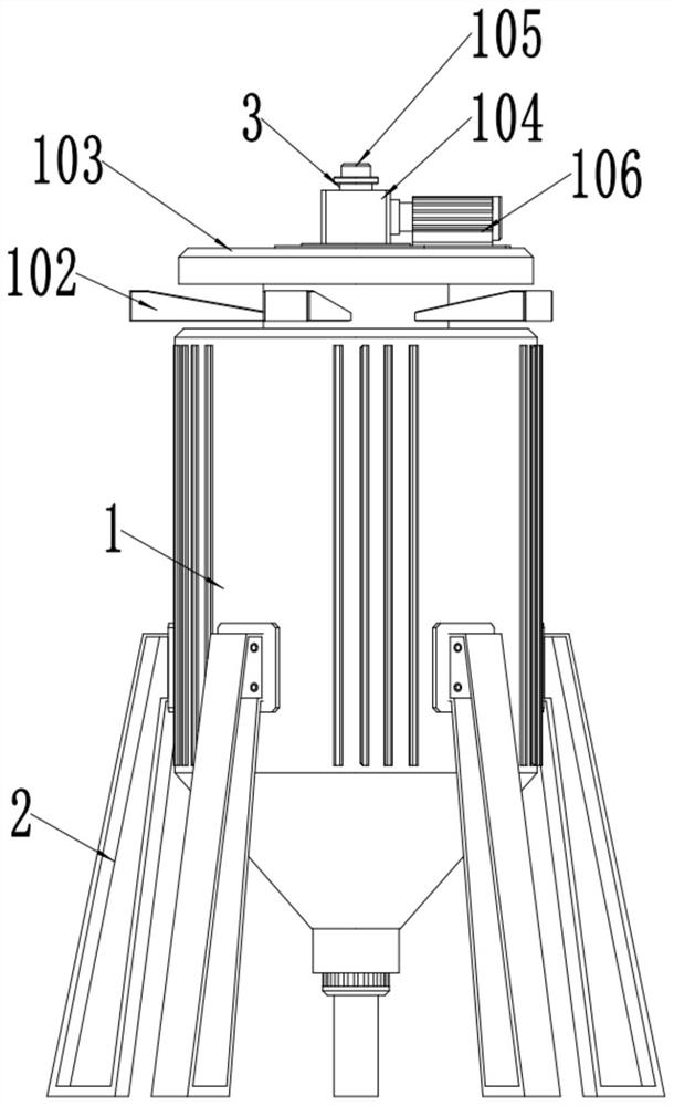
[0029] see Figure 1~2 And 4, in the embodiment of the present invention, a kind of drying equipment that is used for the production of hydroxypropyl methyl cellulose comprises a drying cylinder 1 and a dryer 3 arranged inside the drying cylinder 1, and the inside of the drying cylinder 1 is rotatably installed There is a rotating shaft 301, the rotating shaft 301 is a hollow structure, at least one blade 302 is fixedly installed at the middle position of the rotating shaft 301, and the rotating shaft 301 is located on the upper and lower sides of the blade 302 and is symmetrically provided with a first through hole 303 and a second through hole. A through hole 304; the outside of the drying cylinder 1 is also provided with an air pipe 105, the air pipe 105 communicates with the rotating shaft 301, the air pipe 301 transports hot air to the inside of the rotating shaft 301, and the hot air is discharged from the first through hole 303 and the second through hole 304, After the...
Embodiment 2
[0036] see Figure 1~2And 4, in the embodiment of the present invention, a kind of drying equipment that is used for the production of hydroxypropyl methyl cellulose comprises a drying cylinder 1 and a dryer 3 arranged inside the drying cylinder 1, and the inside of the drying cylinder 1 is rotatably installed There is a rotating shaft 301, the rotating shaft 301 is a hollow structure, at least one blade 302 is fixedly installed at the middle position of the rotating shaft 301, and the rotating shaft 301 is located on the upper and lower sides of the blade 302 and is symmetrically provided with a first through hole 303 and a second A through hole 304; the outside of the drying cylinder 1 is also provided with an air pipe 105, the air pipe 105 communicates with the rotating shaft 301, the air pipe 301 transports hot air to the inside of the rotating shaft 301, and the hot air is discharged from the first through hole 303 and the second through hole 304, After the material enter...
Embodiment 3
[0046] see Figure 4-5 , the discharge of the drying cylinder 1 is provided with a vibrator 4, the vibrator 4 includes a boss 401 and a vibration motor 404, the vibration motor 404 is installed on the discharge of the drying cylinder 1 through a motor base, the vibration motor The upper side of 404 is fixedly installed with at least one connecting bracket 403, and the bottom of described boss 401 is equipped with base plate 402, and described base plate 402 is connected with connecting bracket 403 by buffer spring 405, and vibrating motor 404 produces vibration when working, passes through connecting bracket 403 drives the boss 401 to vibrate, and the dried material contacts with the boss 401 when it falls, and is dispersed under the action of the vibrating boss 401 to prevent the material from agglomerating into blocks;
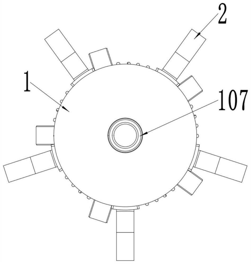
[0047] see image 3 , in the embodiment of the present invention, the outlet of the drying cylinder 1 is provided with an annular outlet 107 for the discha...
PUM
 Abstract
Description
Claims
Application Information
 - R&D
- Intellectual Property
- Life Sciences
- Materials
- Tech Scout
- Unparalleled Data Quality
- Higher Quality Content
- 60% Fewer Hallucinations
Browse by: Latest US Patents, China's latest patents, Technical Efficacy Thesaurus, Application Domain, Technology Topic, Popular Technical Reports.
© 2025 PatSnap. All rights reserved.Legal|Privacy policy|Modern Slavery Act Transparency Statement|Sitemap|About US| Contact US: help@patsnap.com


