
Movable gas turbine power plant waste heat boiler heating surface oxide skin purging device and method

A waste heat boiler and heating surface technology, used in boiler cleaning control devices, combustion methods, and solid residue removal, etc., can solve the adverse effects of header fillet weld strength and life, damaged heating surface pipes, and general ash cleaning effect. and other problems, to achieve the effect of visualization, efficient purging, and improved automation and controllability

Pending Publication Date: 2022-03-15
华能南京燃机发电有限公司
View PDF0 Cites 0 Cited by
  • Summary
  • Abstract
  • Description
  • Claims
  • Application Information

AI Technical Summary

Problems solved by technology

[0004] At present, the commonly used methods of removing scale include sonic purging, steam purging, shock wave purging, mechanical rapping, etc., each of which has its own limitations. For example, although sonic purging has no dead ends and no corrosion, its cleaning effect is average; Although steam blowing can remove the highly adherent scale, it has dead ends; although shock wave blowing has high efficiency, wide adaptability, and simple structure, it is easy to cause damage to the heating surface tube; although mechanical vibration will not damage the Fumes add additional media, but have an adverse effect on the strength and life of header fillet welds
[0005] In order to overcome the limitations of the existing technology, improve the efficiency of waste heat boiler purging and reduce the damage to the heating surface of the waste heat boiler during the purging process, a device and method for purging the oxide skin on the heating surface of the waste heat boiler in a mobile gas turbine power plant are designed.

Method used


Image

  • Movable gas turbine power plant waste heat boiler heating surface oxide skin purging device and method
  • Movable gas turbine power plant waste heat boiler heating surface oxide skin purging device and method

Examples


Embodiment Construction

[0031] It should be noted that, in the case of no conflict, the embodiments of the present invention and the features in the embodiments can be combined with each other. The present invention will be described in detail below with reference to the accompanying drawings and examples.

[0032] In order to make the purpose, technical solutions and advantages of the embodiments of the present invention clearer, the technical solutions in the embodiments of the present invention will be clearly and completely described below in conjunction with the drawings in the embodiments of the present invention. Obviously, the described embodiments It is only some embodiments of the present invention, but not all embodiments. The following description of at least one exemplary embodiment is merely illustrative in nature and in no way taken as limiting the invention, its application or uses. Based on the embodiments of the present invention, all other embodiments obtained by persons of ordina...


PUM


Abstract

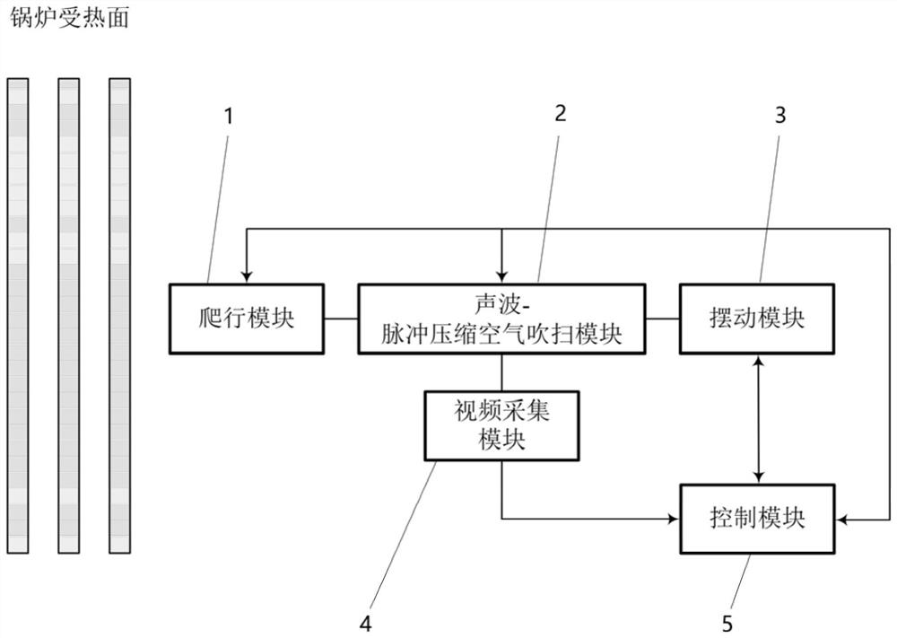
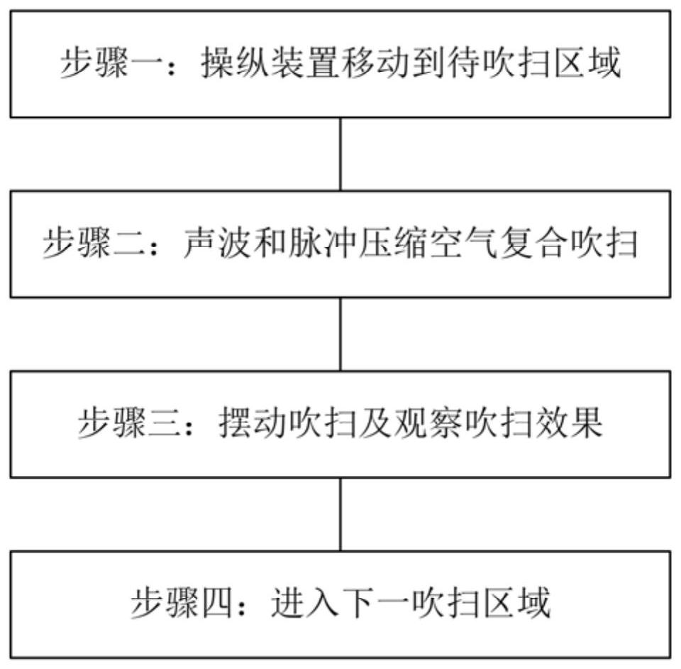
The invention provides a movable gas turbine power plant waste heat boiler heating surface oxide skin purging device and method. The device comprises a crawling module, a sound wave-pulse compressed air purging module, a swing module, a video acquisition module and a control module. The method comprises the steps that the control device moves to a to-be-purged area; sound wave and pulse compressed air composite purging is carried out; blowing by swinging and observing the blowing effect; and entering the next purging area. The advantages of sound wave soot blowing and gas soot blowing are comprehensively utilized, and under the condition that the gas blowing defects are improved and overcome, efficient blowing of the oxide skin on the heating surface of the waste heat boiler is achieved; by adding the swing module, the video acquisition module and the like to the purging device, the purging coverage area is increased, the visualization of the purging process is realized, meanwhile, the whole purging process is recorded, traceable video records are stored, automatic crawling of the purging device within a certain range and remote control of the whole purging process are realized, and the reliability of the purging device is improved. And the automation degree and the controllability of the purging process are improved.

Description

technical field [0001] The invention relates to the technical field of gas turbine power generation, in particular to a device and method for purging scales on the heating surface of waste heat boilers in mobile gas turbine power plants. Background technique [0002] The exhaust gas temperature of the gas turbine is as high as about 600°C, and an oxide film will be formed on the heating surface under high temperature conditions. The oxide film is generally composed of Fe 2 o 3 · Fe 3 Composed of O4·FeO, the thickness is relatively thick. When the thickness increases to a certain critical thickness, it will spontaneously destroy, and peel off and accumulate on the fins. [0003] After the accumulation of scale on the heating surface of the waste heat boiler, the heat transfer capacity of the superheater, evaporator and economizer decreases, resulting in an increase in the flue gas temperature at the waste heat boiler outlet and a decrease in the heat transfer efficiency of ...

Claims


Application Information

Patent Timeline
Patent Type & Authority Applications(China)
IPC IPC(8): F23J3/00F22B37/56
CPCF23J3/00F22B37/56
Inventor 王文一章焰王乾远虞辉濮鸿威徐祥
Owner 华能南京燃机发电有限公司
Learn More