Pipeline shaft and monitoring system and construction method thereof

A technology for pipeline wells and pipelines, which is used in electrical transmission signal systems, artificial islands, measuring devices, etc., can solve the problems of complicated communication pipeline manhole structure, long construction period, poor safety, etc., so as to improve safety and stability. Low cost, not easy to lose the effect

Pending Publication Date: 2022-03-15
JIANGSU SHENCHEN COMM TECH
View PDF0 Cites 0 Cited by
  • Summary
  • Abstract
  • Description
  • Claims
  • Application Information

AI Technical Summary

Problems solved by technology

[0008] The embodiment of the present application provides a prefabricated, integrated, and intelligent pipeline well, which solves the technical problems in the prior art that the manhole structure of the communication pipeline is complex, the construction period is long, the safety is poor, and the cost is high

Method used


Image

  • Pipeline shaft and monitoring system and construction method thereof
  • Pipeline shaft and monitoring system and construction method thereof
  • Pipeline shaft and monitoring system and construction method thereof

Examples


Embodiment 1

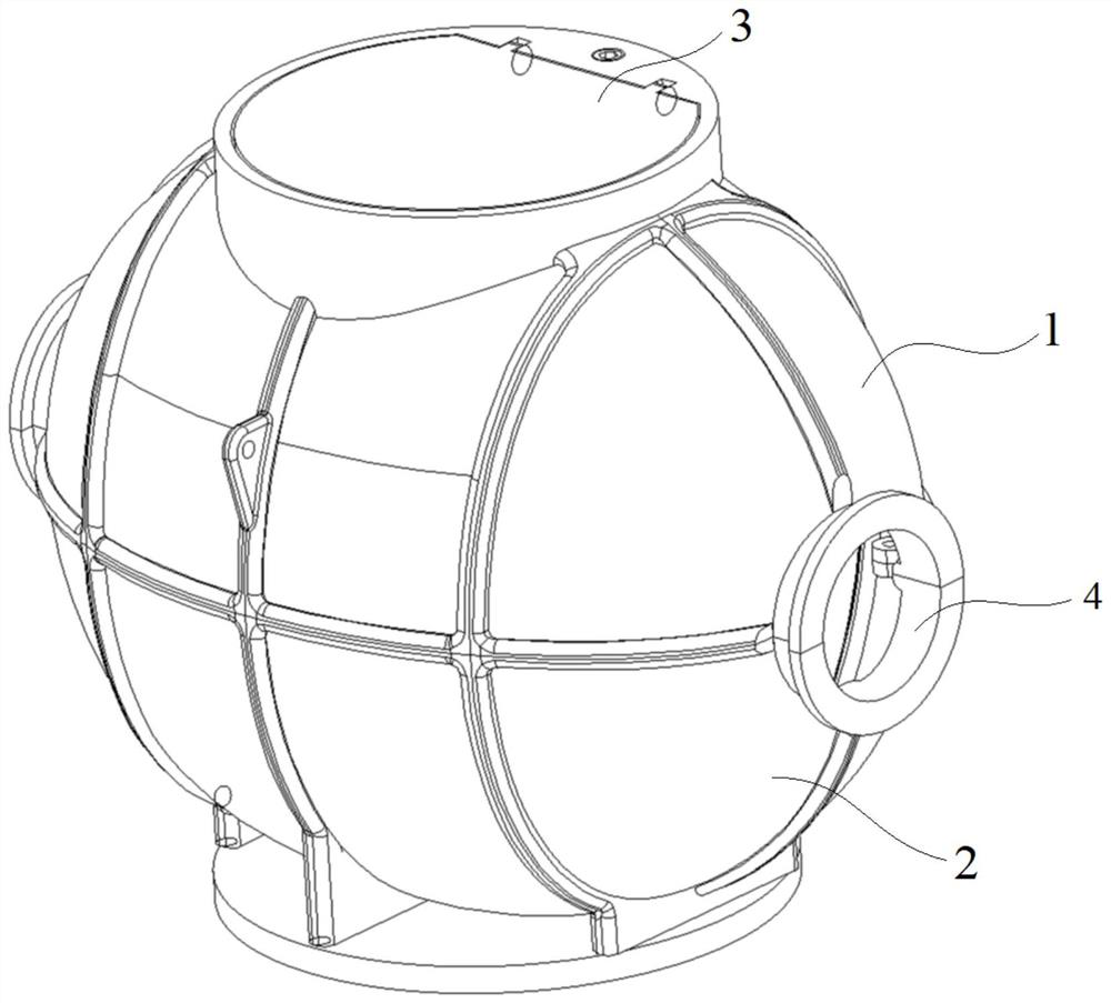
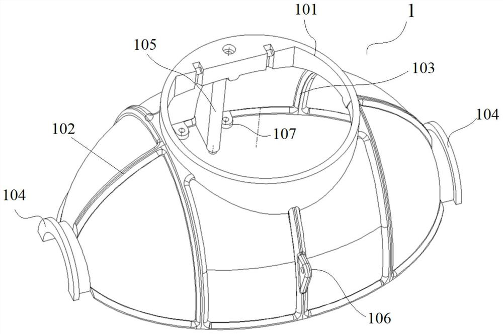
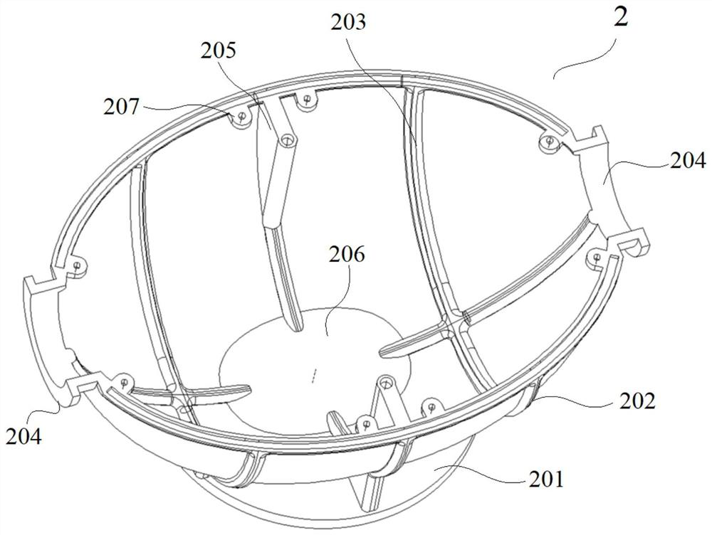
[0068] figure 1 It is a three-dimensional schematic view of the pipeline well provided in the embodiment of the present application. The pipeline well is mainly composed of upper well body 1, lower well body 2, well cover 3, bolts and other components. Both the upper well body 1 and the lower well body 2 are integrally prefabricated, and the well cover 3 is also prefabricated. The upper well body 1 and the lower well body 2 are fixed into an integrated pipeline well body by bolts, and the well cover 3 is rotatably connected with the upper well body 1, so that the installation is convenient and fast.

[0069] The upper well body 1 and the lower well body 2 are combined to form an integral pipeline well body, a cavity is formed inside the pipeline well body, and pipeline windows 4 connected with the cavity are formed at both ends of the pipeline well body, so that communication optical cables can be realized. put on. The pipeline well can be used as a communication pipeline ma...

Embodiment 2

[0115] An embodiment of the present application provides a pipeline well monitoring system, which is used to monitor the status of the above-mentioned pipeline well, including but not limited to the open state of the well cover, the state of the liquid level in the well, the state of the air in the well, and the like. Figure 10 It is a schematic structural diagram of the pipeline well monitoring system provided in the embodiment of the present application, and the pipeline well monitoring system includes:

[0116] The manhole cover monitoring module is set at the position of the manhole cover 3 on the upper well body 1, and is used to monitor the opening state of the manhole cover 3;

[0117] The liquid level sensor is installed in the pipeline well to monitor the state of the liquid level in the well;

[0118] The gas sensor is installed in the pipeline well to monitor the gas state in the well and prevent gas poisoning accidents when the staff work;

[0119] Central proces...


PUM


Abstract

The invention discloses a piping shaft and a monitoring system and a construction method thereof. The piping shaft comprises an upper well body and a lower well body which are integrally prefabricated and formed, a well ring is arranged at the top of the upper well body, and a base is arranged at the bottom of the lower well body; the well lid is arranged on the upper well body and is connected with the well ring in an openable and closable matching manner; the upper well body and the lower well body are spliced and connected into an integral pipeline well body, a cavity is formed in the pipeline well body, and pipeline windows communicated with the cavity are formed in the two ends of the pipeline well body. The pipeline well is divided into the upper well body and the lower well body, the upper well body and the lower well body are integrally prefabricated and formed through high polymer materials and fixed through bolts, and the pipeline well is simple in structure, convenient to install and maintain, short in construction period and low in cost. The pipeline well body is in the shape of an ellipsoid, so that the pipeline well body achieves the maximum compressive strength on unit materials. The opening state of the well lid, the liquid level state in the well, the air state in the well and the like are monitored through the intelligent monitoring system, and the use safety and supervision convenience of the pipeline well are improved.

Description

technical field [0001] The invention relates to the technical field of underground pipeline wells, in particular to a prefabricated, integrated, safe and environment-friendly intelligent pipeline well, a monitoring system and a construction method thereof. Background technique [0002] In the process of threading the optical cable in the underground pipeline, it cannot be threaded in the pipeline without distance restrictions. It is necessary to set at least one communication pipe manhole at a certain distance to facilitate the threading, inspection and maintenance of the communication optical cable. implement. [0003] However, in the process of realizing the technical solution of the invention in the embodiment of the present application, the inventor of the present application found that the above-mentioned technology has at least the following technical problems: [0004] 1. The structure is complex: the existing communication pipeline manholes are mostly composed of se...

Claims


Application Information

Patent Timeline
Patent Type & Authority Applications(China)
IPC IPC(8): E02D29/12E02D29/14E02D29/16E02D31/04G01D21/02G08B7/06G08B21/02H02G9/10
CPCE02D29/121E02D29/124E02D29/1472E02D29/1481E02D29/16E02D31/04G01D21/02G08B7/06G08B21/02H02G9/10
Inventor 殷建伟赵华朱飞
Owner JIANGSU SHENCHEN COMM TECH
Why Eureka
Try Eureka