
Open cut tunnel containing iron sand counterweight layer and construction method of open cut tunnel

A technology of open-cut tunnels and construction methods, which is applied to artificial islands, water conservancy projects, soil protection, etc., can solve the problems of site structure uplift, supporting facilities damage, tunnel structure damage, etc. The effect of a large coefficient of friction

Inactive Publication Date: 2022-03-15
广州市市政工程机械施工有限公司
View PDF5 Cites 0 Cited by
  • Summary
  • Abstract
  • Description
  • Claims
  • Application Information

AI Technical Summary

Problems solved by technology

[0002] For underground structural engineering, when the groundwater level is high, structural anti-floating design is required. Especially for underground traffic tunnel projects, the requirements for lines, elevations, and internal clearance of the structure are relatively strict. If the design cannot meet the structural anti-floating requirements, some sections may Structural uplift, bottom plate cracking, structural dislocation, affecting driving safety, serious cases may even cause large-scale damage to the tunnel structure, damage to related supporting facilities in the tunnel and other serious accidents

Method used


Image

  • Open cut tunnel containing iron sand counterweight layer and construction method of open cut tunnel
  • Open cut tunnel containing iron sand counterweight layer and construction method of open cut tunnel
  • Open cut tunnel containing iron sand counterweight layer and construction method of open cut tunnel

Examples


Embodiment Construction

[0031] The present invention will be described in further detail below in conjunction with specific embodiments.

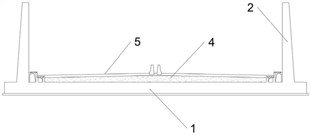
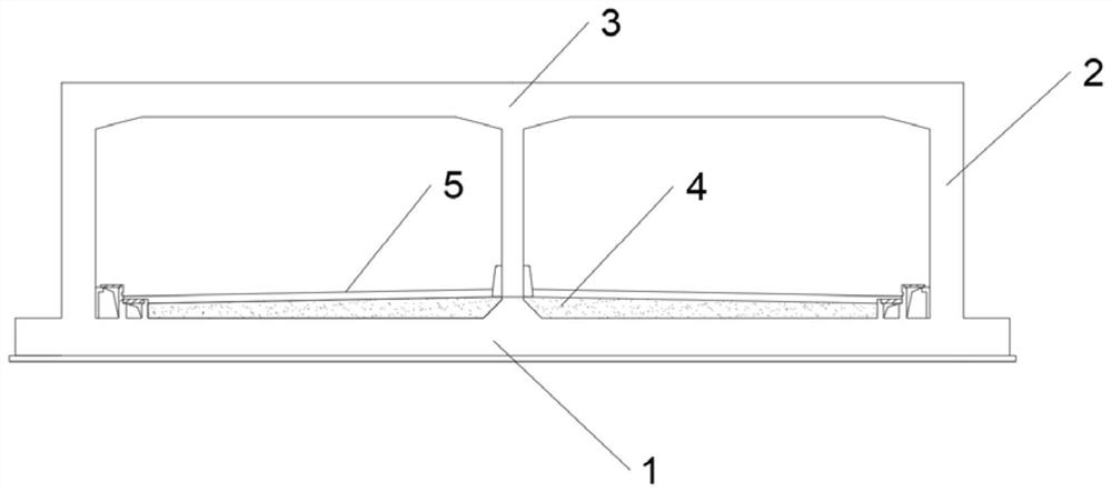
[0032] An open-cut tunnel containing an iron-sand counterweight layer, comprising a tunnel floor, a tunnel side wall, an iron-sand counterweight layer, and an internal road surface of the tunnel; the tunnel side walls are located on the left and right sides of the tunnel floor, and the iron-sand counterweight layer is laid on the upper end of the tunnel floor , The inner pavement of the tunnel is constructed on the upper end surface of the iron sand counterweight layer.

[0033] The iron sand counterweight layer covers the upper end surface of the entire tunnel floor; the iron sand counterweight layer is used for tunnel counterweight and does not participate in the tunnel structure.

[0034] An open-cut tunnel with an iron-sand counterweight layer is divided into a closed section with a tunnel roof and an open section without a tunnel roof.

[0035] In the iron s...


PUM


Abstract

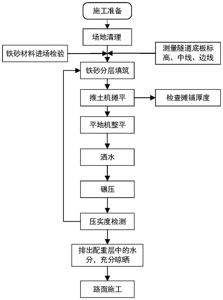
The invention relates to an open-cut tunnel containing an iron sand counterweight layer. The open-cut tunnel comprises a tunnel bottom plate, tunnel side walls, the iron sand counterweight layer and a tunnel internal road surface. The tunnel side walls are located on the left and right sides of the tunnel bottom plate, the iron sand counterweight layer is laid on the upper end face of the tunnel bottom plate, and the tunnel internal road surface is constructed on the upper end face of the iron sand counterweight layer. The invention further relates to a construction method of the open-cut tunnel containing the iron sand counterweight layer. The construction method comprises the following steps that a, the tunnel bottom plate and the tunnel side walls are constructed; b, constructing an iron sand counterweight layer, paving layer by layer, and compacting layer by layer; and c, constructing a tunnel internal pavement including a road pavement base layer and a pavement surface layer. The method is easy and convenient to construct, capable of remarkably improving the dead weight of a tunnel main body structure, obvious in anti-floating effect and used for the portion where the tunnel uplift pile cannot be constructed and belongs to the field of building construction.

Description

technical field [0001] The invention relates to the field of building construction, in particular to an open-cut tunnel with an iron-sand counterweight layer and a construction method thereof, which is used for a site where there is a demand for anti-floating but the anti-lift pile of the tunnel cannot be constructed. Background technique [0002] For underground structural engineering, when the groundwater level is high, structural anti-floating design is required. Especially for underground traffic tunnel projects, the requirements for lines, elevations, and internal clearance of the structure are relatively strict. If the design cannot meet the structural anti-floating requirements, some sections may Structural uplift, floor cracking, and dislocation of structural sections will affect driving safety. In severe cases, it will even cause large-scale damage to the tunnel structure and damage to related supporting facilities in the tunnel and other serious accidents. [0003]...

Claims


Application Information

Patent Timeline
Patent Type & Authority Applications(China)
IPC IPC(8): E02D29/045E02D31/12E02D3/046
CPCE02D29/045E02D31/12E02D3/046
Inventor 张迪欧佳林王刚李超鄢子君首京列绍生杨忠友
Owner 广州市市政工程机械施工有限公司
Learn More